Contracting Multiple IP VPNs
| When an enterprise wants to extend segmentation to the branches, or even interconnect segmented campus networks/MANs, a simple solution is to obtain multiple Layer 3 VPN services from a provider and map each internal VN to a separate service provider Layer 3 VPN. In such a scenario, the branch routers become multi-VRF CEs, and the headend can be either a multi-VRF CE or an E-PE, depending on the segmentation approach used at the headend site. To implement this solution, the enterprise VNs must be terminated at the WAN edge. The interconnection between enterprise VNs and provider VPNs is achieved by connecting VRFs back to back at the enterprise-provider edge. These back-to-back connections involve the use of a subinterface on each pair of VRFs to connect back-to-back logical links between the enterprise VRFs and their corresponding provider VRFs. Routing information must be exchanged over each logical link associated to the subinterfaces. This exchange can be achieved either by a separate instance of an IGP on each subinterface or by a separate eBGP address family peering over the logical link. Table 7-1 outlines the configuration details for an E-PE, P-PE pair. Note that this is similar to a multi-VRF CE-to-PE configuration as described in Chapter 6.
Note In this table, we included only the details pertaining to the back-to-back connection between devices to avoid confusion. Redistribution of the VPN routes in each of the address families is done automatically into eBGP. Figure 7-9 shows three user groups extended to many branch sites. Each user group is mapped to a separate IP VPN service in the provider cloud. Different subinterfaces connect the different VRFs in the E-CE devices with the multiple VRFs in the P-PE devices. These connections provide the mapping between the enterprise VRFs and the service provider VPNs. Figure 7-9. Branch Segmentation Using Multiple Service Provider VPNs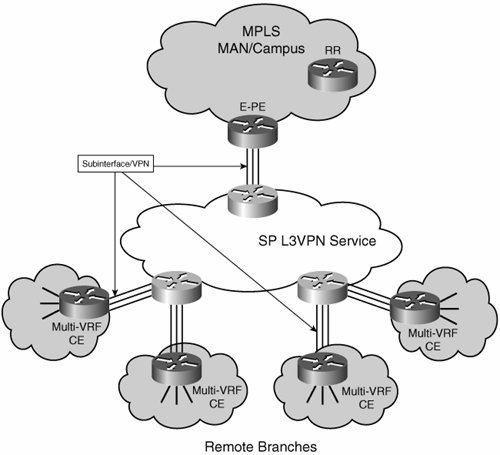 Each CE runs a routing protocol such as OSPF, EIGRP, or BGP with the P-PE on a perVRF basis. All design recommendations and best practices that are applicable to a single VPN service (in terms of routing, quality of service (QoS), multicast, and so on) apply to each of these VPN instances, too. Benefits and DrawbacksBecause of the potential high cost of this approach, it is unlikely to be frequently encountered. Nevertheless, some of the benefits and drawbacks are listed here. The benefits of this approach include the following:
The drawbacks of this approach include the following:
This solution is generally limited to a small number of branches that require segmentation with a low number of VRFs. It can also be implemented among a few campus networks that host only a small number of VNs. The limitation is not necessarily in its scalability, but in its cost. If the service provider bills for each VPN offered, the cost of this service will quickly become unmanageable. Nevertheless, if the service provider offers VPN bundles, this can be a viable solution to support a small number of VNs. Another consideration is the cost of connecting a site to a VPN. If the VPN is also billed by number of connected sites, the use of multiple VPNs might not be suitable for the segmentation of many branches. |
EAN: 2147483647
Pages: 128