6.2 Sample application design
|
| < Day Day Up > |
|
6.2 Sample application design
The EMF and GEF sample application is an Eclipse plug-in. It is an editor, which uses a property view to capture user input, and provides an outline view to help the user to navigate more easily through the model. It also has multiple levels of undo and redo, and provides several Eclipse plug-in extension points.
These plug-in extension points are:
-
The view menu, which contains the Zoom In and Zoom Out menu items
-
The undo, redo tool bar
At the editor level, additional context dependent features have been defined:
-
Inplace editing for compound tasks:
-
A task can be added to a compound task by means of drag and drop.
-
A sub-workflow can be accessed through the compound task itself.
-
-
A separate editor tab for compound task editing:
-
This provides an extended work space to work on a sub-workflow defined in a compound task.
-
-
During edge creation, which is a link between two nodes, the link creation tool is smart enough to recognize where the link can be connected:
-
No loop on a single task is allowed.
-
No link from a task of a sub-workflow to a task in the main workflow is allowed.
-
Link cursor is dynamically updated to represent the ability to connect to a given endpoint.
-
-
Dynamic update of the main and properties view, to reflect the user action on the outline view.
-
Drag and drop from the palette into the viewer.
-
Right-click contextual menu:
-
For example, the Choice right-click menu contains undo, delete, add condition to choice and save actions.
-
6.2.1 Design decisions
During the design process, we made some important decisions, including these:
-
There is one top level workflow per file.
-
The sub-workflow of a compound task is contained in the workflow itself. No reference to an external workflow or sub-workflow is supported.
| Note | In Eclipse, only one editor can be opened on a workflow at a time, but multiple workflows can be edited in different Eclipse workflow editors. |
6.2.2 The workflow model
This section documents the WorkflowModel, shown in Figure 6-5.
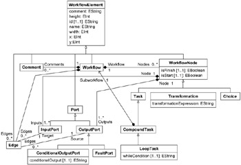
Figure 6-5: The WorkflowModel
WorkflowElement
The WorkflowElement class provides features common to all elements present in a workflow. It is the common abstract supertype of the Workflow, WorkflowNode Port, Edge and Comment classes. Table 6-1 provides a summary of the WorkflowElement class.
| Owned By | |
| Inheritance | |
| Features | name: Identifies the Workflow comment: An optional comment string x: Coordinate used for layout y: Coordinate used for layout width: Used for layout of container elements height: Used for layout of container elements id: Used to uniquely identify a workflow element |
| Constraints |
Workflow
The Workflow class represents the description of a process. A Workflow contains WorkflowNodes representing the steps in the process and Edges that represent data and control flow between the nodes. A Workflow may also contain comments that annotate the process described by the Workflow. Table 6-2 provides a summary of the Workflow class.
| Owned By | |
| Inheritance | WorkflowElement |
| Features | nodes: The WorkflowNodes contained within this Workflow edges: The Edges contained within the Workflow comments: The Comments contained within the Workflow |
| Constraints |
WorkflowNode
The class WorkflowNode represents a step in a Workflow. WorkflowNodes have ports and may be connected to other WorkflowNodes via those ports. Table 6-3 provides a summary of the WorkflowNode class.
| Owned By | |
| Inheritance | WorkflowElement |
| Features | isStart: Indicates whether this is the starting node of a Workflow isFinish: Indicates whether this is the finishing node of a Workflow workflow: A reference to the Workflow that contains the node outputs: Output ports (including fault ports) owned by the node inputs: Input ports owned by the node |
| Constraints | WorkflowNodes have no more than one Fault port. |
Task
The class Task represents an action or unit of work within the Workflow.
The start and end icons in the documentation are different from the ones currently implemented. In the application, the start task's InputPort is replaced by a green square and the end task's OutputPort is replaced by a red square as shown in Figure 6-6.
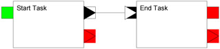
Figure 6-6: Task visual
Table 6-4 provides a summary of the Task class.
| Owned By | |
| Inheritance | WorkflowNode |
| Features | |
| Constraints | A Task has exactly one input port and one (non-fault) output port. |
CompoundTask
The class CompoundTask is a Task that is defined by a sub-workflow. The CompoundTask is complete when the sub-workflow that composes it is complete. As CompoundTask inherits from Task, it has a single input port, output port and fault port. When a CompoundTask begins, the inputs to the start nodes of the sub-workflow are the inputs that are received at the input port of the CompoundTask. Similarly, when the sub-workflow completes, the output data from the finishing nodes of the sub-workflow provide the data that is output from the output port of the CompoundTask. Figure 6-7 shows the visual representation of a CompoundTask.
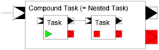
Figure 6-7: Compound task visual
Table 6-5 provides a summary of the CompoundTask class.
| Owned By | |
| Inheritance | Task |
| Features | subworkflow: The Workflow that defines the CompoundTask |
| Constraints |
LoopTask
The LoopTask represents actions that are repeated while a condition is true. The actions that are repeated are contained by the sub-workflow of the LoopTask. The data received at the Input of the LoopTask is provided as the input to the first execution of the start node in the LoopTask's sub-workflow. For each repetition of the sub-workflow, the output from the previous execution becomes the input to the current one. The output from the finishing nodes from the final execution of the loop becomes the output of the LoopTask. Figure 6-8 shows the visual representation of the LoopTask
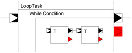
Figure 6-8: LoopTask visual
Table 6-6 provides a summary of the LoopTask class.
| Owned By | |
| Inheritance | CompoundTask |
| Features | whileCondition: While this holds, the sub-workflow is repeated |
| Constraints |
Choice
The class Choice represents a switch between alternative execution and data flow paths. Data and control flow is only activated for Edges that source from output ports of the Choice where the condition of the OutputPort evaluates to true. Conditions must be unique in a Choice. The default name for a condition is false.
The way conditions are represented in the workflow editor differ a little bit from the present documentation, where a condition is drawn close to the corresponding edge. In the editor, they are drawn inside the Choice visual itself. A condition is placed in front of the corresponding ConditionalOutputPort port, see Figure 6-9.
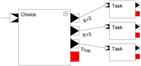
Figure 6-9: Choice visual
| Note | The little icon on the upper right corner of the Choice is used for adding a condition to it. If you click it and nothing happens, check if the default false condition is not already defined in the Choice. |
Table 6-7 provides a summary of the Choice class.
| Owned By | |
| Inheritance | WorkflowNode |
| Features | |
| Constraints | Choice has only one input port, but may have multiple output ports. Non-fault OutputPorts owned by a Choice must be ConditionalOutputPorts. |
Transformation
The class Transformation takes multiple inputs and performs a transformation on that data to produce a single result. Figure 6-10 shows the visual representation of a Transformation.
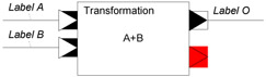
Figure 6-10: Transformation task visual
Table 6-8 provides a summary of the Transformation class.
| Owned By | |
| Inheritance | WorkflowNode |
| Features | transformExpression: Expresses how the input data is transformed into the output data |
| Constraints | Transformation has only one (non-fault) output port, but may have multiple input ports |
Edge
The class Edge represents a connection between an output port and an input port, that is, a flow of data from the output of one WorkflowNode to the input of another. Table 6-9 provides a summary of the Edge class.
| Owned By | Workflow |
| Inheritance | WorkflowElement |
| Features | workflow: The containing Workflow source: The output port from which the Edge begins target: The input port at which the Edge terminates |
| Constraints |
Port
The abstract class Port is the common supertype for InputPort and OutputPort.Table 6-10 provides a summary of the Port class
| Owned By | |
| Inheritance | WorkflowElement |
| Features | |
| Constraints |
InputPort
The class InputPort represents the Port at which data and control is received by a node in the Workflow. Table 6-11 provides a summary of the InputPort class
| Owned By | WorkflowNode |
| Inheritance | Port |
| Features | edges: The edges that target the InputPort node: The WorkflowNode that owns the InputPort |
| Constraints |
OutputPort
The class OutputPort represents the Port at which data and control is provided by a WorkflowNode upon completion. Table 6-12 provides a summary of the OutputPort class.
| Owned By | WorkflowNode |
| Inheritance | Port |
| Features | node: The WorkflowNode that owns the OutputPort edges: The edges for which the OutputPort is the source |
| Constraints |
FaultPort
FaultPort represents the output of a node that terminates under exceptional conditions. The exception may be handled by another node if there is an Edge linking the FaultPort with the InputPort of the handling WorkflowNode, otherwise the Workflow containing the WorkflowNode that owns the FaultPort fails. Table 6-13 provides a summary of the FaultPort class
| Owned By | |
| Inheritance | OutputPort |
| Features | |
| Constraints |
ConditionalOutputPort
The ConditionalOutputPort class represents an output of a Choice. For any Choice, the conditions of its ConditionalOutputs determine the execution paths that are taken upon evaluation of the Choice, as only Edges sourcing from a ConditionalOutputPort where the condition evaluates to true will be activated when the Choice completes. Table 6-14 provides a summary of the ConditionalOutputPort class
| Owned By | |
| Inheritance | OutputPort |
| Features | condition: The condition used to determine the execution path |
| Constraints |
Comment
The Comment class represents a free-standing comment within a Workflow. The text of the comment is represented in the comment attribute inherited from WorkflowElement. The Comment class provides a mechanism for including comments in the workflow that are not attached to the Ports, Edges or WorkflowNodes. Table 6-15 provides a summary of the Comment class.
| Owned By | Workflow |
| Inheritance | WorkflowElement |
| Features | |
| Constraints |
|
| < Day Day Up > |
|
EAN: 2147483647
Pages: 70