Understanding Text Formatting in AutoCAD
AutoCAD offers a wide range of text-formatting options. You can control fonts, text height, justification, line spacing, and width. You can even include special characters such as degree symbols or stacked fractions. In a departure from the somewhat clumsy text implementation of earlier AutoCAD versions, you now have a much wider range of controls over your text.
Adjusting the Text Height and Font
Let's continue our look at AutoCAD text by adding a label for the living room of the studio apartment. You'll use the Multiline Text tool again, but this time you'll get to try out some of its other features.
In this first exercise, you'll see how you can adjust the size and font of text in the editor:
-
Pan your view so that the kitchen is just at the top of the drawing, as shown in the first image in Figure 8.2.
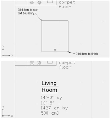
Figure 8.2: Placing the text boundary window for the living room label and the final label -
Click the Multiline Text tool again; then select a text boundary window, as shown in the first image in Figure 8.2.
-
In the text editor, start typing the following text:
Living Room
14 ¢ -0 ² by 16 ¢ -5 ²
[427 cm by 500 cm]As you type, notice that the words Living and Room become two separate lines even though you did not press
 between them. AutoCAD uses word wrap to fit the text inside the text boundary area.
 -
Highlight the text 14 ¢ - ² by 16 ¢ - 5 ² [427 cm by 500 cm] as you would in any word processor. For example, you can click the end of the line to place the cursor there; then Shift+click the beginning of the line to highlight the whole line.
-
In the Text Formatting toolbar, click the Text Height drop-down list and select 6. The highlighted text changes to a smaller size.
-
Highlight the words Living Room.
-
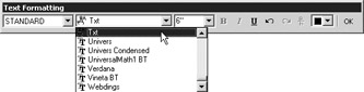
Click the Font drop-down list to display a list of font options.
-
Scroll up the list until you find Arial. This is a standard TrueType font available in all installations of Windows NT and Windows XP. Notice that the text in the text editor changes to reflect the new font.
-
 With the words Living Room still highlighted, click the Underline button in the Text Formatting toolbar.
 -
Click OK in the Text Formatting toolbar. The label appears in the area you indicated in step 2 (see the bottom image in Figure 8.2).
-
Now to see how you might go back to the Text Formatting toolbar, double-click the text. The Text Formatting toolbar and text editor appear, enabling you to make changes to the text.
-
Click OK to exit the Text Formatting toolbar.
While using the Multiline Text tool, you might have noticed the [Height/Justify/Line spacing/ Rotation/Style/Width]: prompt immediately after you picked the first point of the text boundary. You can use any of these options to make on-the-fly modifications to the height, justification, line spacing, rotation style, or width of the multiline text.
For example, after clicking the first point for the text boundary, you can type R ![]() and then specify a rotation angle for the text window, either graphically with a rubber-banding line or by entering an angle value. After you've entered a rotation angle, you can resume selecting the text boundary.
and then specify a rotation angle for the text window, either graphically with a rubber-banding line or by entering an angle value. After you've entered a rotation angle, you can resume selecting the text boundary.
| |
If you have PostScript fonts that you would like to use in AutoCAD, you need to compile them into Auto- CAD's native font format. To do so, follow these steps:
-
Type Compile
to open the Compile Shape Or Font File dialog box. -
Select PostScript Font (*.pfb) from the File Of Type drop-down list, and then browse to find the font you want to convert.
-
Double-click the PostScript font you want to convert into the AutoCAD format. AutoCAD will work for a moment; then you'll see this message:
"Compiling shape/font description file"
Compilation successful. Output file Program Files\AutoCAD2005\ FONTS\ fontname.shx
contains 59578 bytes.
When AutoCAD is finished, you have a file with the same name as the PostScript font file but with the .shx filename extension. If you place your newly compiled font in AutoCAD's Fonts folder, it will be available in the Style dialog box.
When you work with AutoCAD's .shx font files, it is important to remember the following:
-
License restrictions still apply to the AutoCAD-compiled version of the PostScript font.
-
Like other fonts, compiled PostScript fonts can use up substantial disk space, so compile only the fonts you need.
| |
Scaling Multiple Text Objects in a Hurry
Another way to quickly change the size of text is to use the Scaletext command. Choose Modify Object Text Scale, or type Scaletext at the command prompt, and then select the text you want to scale. You can select multiple text objects. Press ![]() when you've completed your selection. You see this prompt:
when you've completed your selection. You see this prompt:
[Existing/Left/Center/Middle/Right/TL/TC/TR/ML/MC/MR/BL/BC/BR/]<TL>:
Enter the letters corresponding to the justification option you want to use for the text (see "Justifying Single-Line text Objects" later in this chapter). (See the section "Justifying Single-Line Text Objects" later in this chapter for a description of these options.) After you've entered an option, you see the next prompt:
Specify new height or [Match object/Scale factor] < Current height >:
At this prompt you have three options:
-
Enter a new height
-
Type M
and select another text object whose height you want to match -
Type S
and enter a scale factor to scale the text to a specific ratio
Adding Color , Stacked Fractions, and Special Symbols
In the previous exercise, you were able to adjust the text height and font, just as you would in any word processor. You saw how you can easily underline portions of your text by using the tool buttons in the editor. Other tools enable you to set the color for individual characters or words in the text, create stacked fractions, or insert special characters. Here's a brief description of how these tools work:
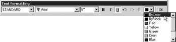
To change the color of text , highlight it and then select the color from the Text Color drop- down list.
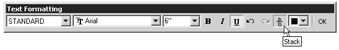
To turn a fraction into a stacked fraction , highlight the fraction and then click the Stack/Unstack tool.
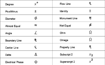
To add a special character , place the cursor at the location where you want the character placed , right-click, and then choose Symbol from the shortcut menu.
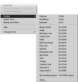
The Symbol option offers several commonly used symbols that you can add to your drawing. Also include is the non-breaking space option which add a space that will not break into separate lines unless the text boundary is too narrow.
When you select these options, AutoCAD inserts the proper AutoCAD text code in the text that corresponds to these symbols. You'll get a more detailed look at special symbols later in this chapter.
Adjusting the Width of the Text Boundary Window
Although the font and height of your text are formatted correctly, the block of text appears too tall and narrow. The following steps will show you how to change the boundary to fit the text:
-
Click any part of the text you just entered to highlight it.
-
Click the upper-right grip.
-
Drag the grip to the right, to the location shown in Figure 8.3; then click that point.
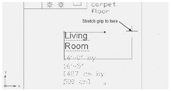
Figure 8.3: Adjusting the text boundary window -
Click any grip, and then right-click the mouse and choose Move.
-
Move the text to a location that is more centered in the room.
AutoCAD's word-wrap feature automatically adjusts the text formatting to fit the text boundary. This feature is especially useful to AutoCAD users because other drawing objects often affect the placement of text. As your drawing changes, you will need to adjust the location and boundary of your notes and labels.
Adjusting the Text Alignment
The text is currently aligned on the left side of the text boundary. For a label such as the one in the living room, it is more appropriate to center the text.
Here's how you can make changes to the text alignment:
-
Double-click the text to display the Text Formatting toolbar. You can also right-click the text after selecting it and then select Mtext Edit from the shortcut menu. Or, from the menu bar, choose Modify Object Text Edit.
-
Right-click the text and then choose Justification Top Center from the shortcut menu. The living room label moves to a centered position above the second line.
-
Click OK. The text changes to align through the center of the text, as shown in Figure 8.4.
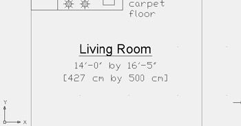
Figure 8.4: The text aligned using the Top Center alignment option
You can also change the justification of text through the Properties palette. Select the multiline text you want to edit, and then right-click and choose Properties from the shortcut menu. Click the setting just to the right of the Justify option. It becomes a drop-down list. Open the list and select the justification style you want. The text changes as you select the justification style.
| Tip | You can open the Text Formatting toolbar from the Properties palette. Right-click the text after selecting it; then choose Properties to open the Properties palette. You can then select the Contents option and click the ellipsis button that appears to the far right of the option. |
Text Alignment and Osnaps
Although it's clear that the text is now aligned through the center of the text boundary, one important change occurred that is not so obvious. You might have noticed that the object alignment list offered three centered options: Top Center, Middle Center, and Bottom Center. All three of these options have the same effect on the text's appearance, but they each have a different effect on how Osnaps act upon the text. Figure 8.5 shows where the Osnap point occurs on a text boundary, depending on which alignment option is selected. A multiline text object has only one insertion point on its boundary that you can access with the Insert Osnap.
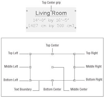
Figure 8.5: The location of the Insert Osnap points on a text boundary based on its alignment setting
The Osnap point also appears as an extra grip point on the text boundary when you click the text. If you click the text you just entered, you will see that a grip point now appears at the top center of the text boundary.
Knowing where the Osnap points occur can be helpful when you want to align the text with other objects in your drawing. In most cases, you can use the grips to align your text boundary, but the Top Center and Middle Center alignment options enable you to use the center and middle portions of your text to align the text with other objects.
Changing Justification of Multiple Text Objects
You've seen how you can change the justification of an individual text object, but you will often find that you need to change the justification of several text objects at one time. AutoCAD offers the Justifytext command for this purpose. To use it, choose Modify Object Text Justify, or type Justifytext ![]() at the command prompt. At the Select object: prompt, select the text you want to change, and then press
at the command prompt. At the Select object: prompt, select the text you want to change, and then press ![]() to confirm your selection. You'll see the following prompt in the command line:
to confirm your selection. You'll see the following prompt in the command line:
[Left/Align/Fit/Center/Middle/Right/TL/TC/TR/ML/MC/MR/BL/BC/BR] <BC>:
Enter the letters corresponding to the type of justification you want to use for the text. (See the section "Justifying Single-Line Text Objects" later in this chapter for a description of these options.) After you've entered an option, the selected text will change to conform to the selected justification option.
Setting Indents and Tabs
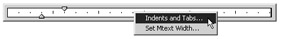
You'll also want to know about the indent and tab features of the Text Formatting toolbar's text window. You might have noticed the ruler at the top of the text editor. Figure 8.6 shows that ruler, including tab and indent markers.
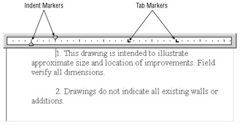
Figure 8.6: The ruler at the top of the text editor lets you quickly set tabs and indents for text.
The indent markers let you control the indention of the first line and the rest of the paragraph. The tab markers give you control over tab spacing. For new text, the tab markers don't appear until you add them by clicking the ruler. The following exercises will demonstrate the use of these markers more clearly.
Start by practicing with the indent markers:
-
On the CD Open the Indents.dwg file from the companion CD. This file contains some text that you will experiment with.
-
Double-click the text at the top of the drawing to open the Text Formatting toolbar.
-
Press Ctrl+A to highlight all the text in the text editor. This is necessary to indicate the group of text to be affected by your indent settings.
-
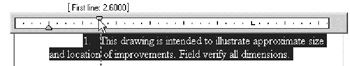
Click and drag the top indent marker two spaces to the left. Notice that the indent of the first line moves with the marker. A note appears above the ruler showing you how much indent you are applying. Also notice that the text at the first tab remains at its starting location.
-
Click and drag the bottom indent marker two spaces to the left. Notice that the rest of the paragraph moves with the marker. Again, you see a note by the ruler showing you how much indent you are applying.
Here you see how you can control the indents of the selected text with the indent markers. You can set different paragraphs of a single Mtext object differently, giving you a wide range of indent- formatting possibilities. Just select the text you want to set and then adjust the indent markers.
Now try the tab markers. For this exercise you will try the text import feature to import a tab- delimited text file:
-
Click the Multiline Text tool on the Draw toolbar.
-
For the first corner, click the upper-left corner of the large rectangle in the drawing just below the paragraph.
-
For the opposite corner, click the lower-right corner of the rectangle.
-
Right-click in the text editor of the Text Formatting toolbar and select Import Text.
-
On the CD In the Select File dialog box, locate and select the Tabtest.txt file from the Chapter 8 files from the companion CD. The contents of the Tabtest.tx t file are displayed in the text editor.
The file you just imported was generated from the Attribute Extraction feature of AutoCAD. You'll learn more about this feature in Chapter 10. The important thing to note is that this file contains tabs to align the columns of information. You can adjust those tabs in the Text Formatting toolbar, as you'll see in the next set of steps.
Now use the tab markers to adjust the tab spacing of the columns of text:
-
Press Ctrl+A to select all the text.
-
Click the ruler at a point that is at the 12th mark from the left. An L-shaped marker appears, and the first tab column of text moves to this position.
-
Click the ruler again at the 20th mark. The second column aligns to this position.
-
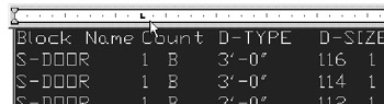
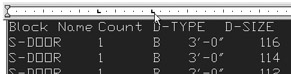
Continue to click the ruler to add more tab markers so that the text looks similar to Figure 8.7. Don't worry about being exact. This is just for practice. After you've placed a marker, you can click and drag it to make adjustments.
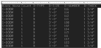
Figure 8.7: Add tab markers so that your text looks similar to this figure. -
Click Close on the Text Formatting toolbar. The text appears in the drawing as a door schedule.
Here you saw how you can create a table or a schedule from an imported text file. You can also create a schedule from scratch by composing it directly in the text editor of the Text Formatting toolbar. Prior to AutoCAD 2005, this was the only method available for creating this type of table, but AutoCAD now offers the Table feature specifically designed for creating tables (see "Adding Tables to your Drawing" later in this chapter). Still, this example offers a way to demonstrate the tab feature in the Multiline Text tool, and you may encounter a file in which a table is formatted in the way described here.
Besides using the indent and tab markers on the ruler, you can also control indents and tabs through the Indents And Tabs dialog box. Do the following to get a firsthand look:
-
Double-click the text at the top of the Indents.dwg drawing (the one you edited in the first part of this section) and then press Ctrl+A to select all the text.
-
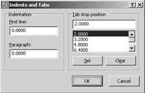
Right-click the ruler above the text editor and then click Indents And Tabs.
The Indents And Tabs dialog box appears.
-
Change the value in the Paragraph input box to 2.2 .
-
Double-click the Tab Stop Position input box in the upper-right corner and enter 2.2
. You can also click the Set button instead of pressing . -
Click OK. Notice that the text now appears with the text indented from the numbers .
-
Close the Text Formatting toolbar. Notice how the text in the drawing is now formatted as it appeared in the text editor of the Text Formatting toolbar.
-
Exit the Indents.dwg file.
In this exercise, you used the Indents And Tabs dialog box to set the paragraph indent and the first tab marker to be the same value. This causes the text portion of the list to be aligned at a distance of 2.2 drawing units from the left text boundary, leaving the list number extended farther to the left. This gives the list a more professional appearance.
The Indents And Tabs dialog box gives you fine control over the formatting of your text. It lets you delete tabs by highlighting the tab in the list and clicking the Clear button. You can also add tabs at specific distances from the left margin of the text boundary by entering new tab locations in the Tab Stop Position input box and clicking the Set button.
You specify distances in drawing units. If your drawing is set up to use Architectural units, for example, you can enter values in feet and inches or just inches. The First Line and Paragraph input boxes let you enter a numeric value for paragraph indents. As you have just seen, you can use the First Line and Paragraph input boxes to create a numbered list by setting the Paragraph input box value to be the same as the first tab stop position.
| Tip | You might have noticed the Set Mtext Width right-click option in step 2 of the preceding exercise. This option opens a simple dialog box that enables you to enter a width for the text boundary. You can also click and drag the right inside edge of the ruler to change the text boundary width. |
Adjusting Line Spacing
Another text-editing feature that is related to text indents and tabs is the Line Spacing option. You can adjust line spacing between the range of 0.5 and 4 times the height of the text. Here's how it works:
-
Go back to the Unit drawing, select the words Living Room, and then right-click.
-
Choose Properties from the shortcut menu to open the Properties palette.
-
Use the scroll bar at the left of the Properties palette to scroll down until you see all of the entries in the Text group.
-
Double-click the Line Space Factor value in the Text group.

-
Enter 4
. The value changes to reflect the spacing of the text at 4 times the height of the text. -
Close the Properties palette. You see that the line spacing of the selected text has changed.
-
Type U
or click the Undo button in the Standard toolbar. You don't need to save this change to the text.
In step 5 you entered 4 to indicate that you want a line-spacing value that is 4 times the text height. Just below the Line Space Factor option in the Properties palette, you will see the Line Space Style option. This enables you to choose between an approximate spacing and an exact spacing.
Editing Text Content
It is helpful to think of text in AutoCAD as a collection of text documents. Each text boundary window you place is like a separate document. You've already seen how to change the formatting of text by using the Text Formatting toolbar. Now try changing the contents. This time, you'll try out the Ddedit command, which works in a slightly different way from the usual double-click method:
-
Choose Modify Object Text Edit, or type Ddedit
at the command prompt. -
Click the words Living Room to display the Text Formatting toolbar along with the text editor.
-
Place and click the text cursor on the end of the line that reads Living Room, and then type
230 square feet . -
Click OK. The text appears with the additional line in the drawing.
-
The Ddedit command is still active, so press
to exit Ddedit.
In step 5, the Ddedit command remained active so that you could continue to edit other text objects. If you wanted to make additional changes, you could have selected another text object to change before pressing ![]() to exit the Ddedit command.
to exit the Ddedit command.
As with the previous exercise, you can change the formatting of the existing or new text while in the text editor of the Text Formatting toolbar. Notice that the formatting of the new text is the same as the text that preceded it. Just as in Microsoft Word, the formatting of text depends on the paragraph or word to which it is added. If you had added the text after the last line, it would appear in the AutoCAD Txt font and in the same 6 ² height.
| Tip | You can highlight text in the text window, and then click and drag to move it, or Ctrl+click and drag to copy it. |
Converting Text to Lowercase or Uppercase
If you find that you need to change the case of existing text, you can do so with the shortcut menu while in the Text Formatting toolbar. Here are the steps (you don't need to apply these steps to your drawing exercises):
-
Double-click a multiline text object.
-
Highlight the text you want to change.
-
Right-click, and then choose Change Case Uppercase or choose Change Case Lower- case, depending on which option you want.
-
Click Close to exit the Text Formatting toolbar.
Tip There is an AutoCAPS option in the Text Editor shortcut menu that enables you to turn on Caps Lock. This can be handy when you import text that needs to be in all uppercase letters.
Understanding Text and Scale
In the first few exercises of this chapter, you were asked to make the text height 6 ² . This is necessary to give the text the proper scale for the drawing. But where did we come up with the number 6? Why not 4 or 10? The 6 ² height was derived by carefully considering the desired final height of the text in relation to the designated scale of the drawing. Just as in Chapter 3, where you applied a scale factor to a drawing's final sheet size to accommodate a full-scale drawing, you need to make a scale conversion for your text size to make the text conform to the drawing's intended scale.
Text-scale conversion is a concept many people have difficulty grasping. As you discovered in previous chapters, AutoCAD enables you to draw at full scale, that is, to represent distances as values equivalent to the actual size of the object. When you later plot the drawing, you tell AutoCAD the scale at which you want to plot, and the program reduces the drawing accordingly . This allows you the freedom to enter measurements at full scale and not worry about converting them to various scales every time you enter a distance. Unfortunately, this feature can also create problems when you enter text and dimensions. Just as you had to convert the plotted sheet size to an enlarged size equivalent at full scale in the drawing editor, you must convert your text size to its equivalent at full scale.
To illustrate this point, imagine you are drawing the Unit plan at full size on a very large sheet of paper. When you are finished with this drawing, it will be reduced to a scale that enables it to fit on an 8.5 ² 11 ² sheet of paper. So you have to make your text quite large to keep it legible after it is reduced. This means that if you want text to appear 1 / 8 ² high when the drawing is plotted, you must convert it to a considerably larger size when you draw it. To do this, you multiply the desired height of the final plotted text by a scale conversion factor.
If your drawing is at a 1 / 8 ² = 1 ¢ -0 ² scale, you multiply the desired text height, 1 / 8 ² , by the scale conversion factor of 96 to get a height of 12 ² . This is the height you must make your text to get 1 / 8 ² -high text in the final plot. (Chapter 3 shows scale factors as they relate to standard drawing scales.) Table 8.1 shows you some other examples of text height to scale.
| Drawing Scale | Scale Factor | AutoCAD Drawing Height for 1 / 8 ² -High Text |
|---|---|---|
| 1 / 16 ² = 1 ¢ -0 ² | 192 | 24.0 ² |
| 1 / 8 ² = 1 ¢ -0 ² | 96 | 12.0 ² |
| ¼ ² = 1 ¢ -0 ² | 48 | 6.0 ² |
| ½ ² = 1 ¢ -0 ² | 24 | 3.0 ² |
| ¾ ² = 1 ¢ -0 ² | 16 | 2.0 ² |
| 1 ² = 1 ¢ -0 ² | 12 | 1.5 ² |
| 1 ½ ² = 1 ¢ -0 ² | 8 | 1.0 ² |
| 3 ² = 1 ¢ -0 ² | 4 | 0.5 ² |
EAN: 2147483647
Pages: 261