Adding Text to a Drawing
In this first section, you will add some simple labels to your Unit drawing to identify the general design elements: the bathroom, the kitchen, and the living room.
Start by setting up a drawing to which you can apply some text:
-
On the CD Start AutoCAD and open the Unit file. If you haven't created the Unit file, you can use the file called 08a-unit.dwg from the companion CD. Metric users should use 08a-unit-metric.dwg. After it is open, choose File Save As to save the Unit drawing to a file called Unit.dwg .
-
Create a layer called Notes and make it the current layer. Notes is the layer on which you will keep all your text information.
-
Turn off the Flr-pat layer. Otherwise, the floor pattern you added previously will obscure the text you enter during the exercises in this chapter.
Tip It's a good idea to keep your notes on a separate layer, so you can plot drawings containing only the graphics information or freeze the Notes layer to save redraw /regeneration time.
-
Set up your view so it looks similar to the top image in Figure 8.1.
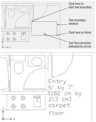
Figure 8.1: The top image shows the points to pick to place the text boundary window. The bottom image shows the completed text.
You've got the drawing ready. Now add some text:
-
 Choose Draw Text Multiline Text from the menu bar, or type MT
  . You can also select the Multiline Text tool from the Draw toolbar.You'll see a prompt that tells you the current text style and height:
 Current text style "STANDARD"Text height: 9 1 / 16 "
Specify first corner:
-
Click the first point indicated in the top image in Figure 8.1 to start the text boundary window. This boundary window indicates the area in which to place the text. Notice the arrow near the bottom of the window. It indicates the direction of the text flow.
Tip You don't have to be too precise about where you select the points for the boundary because you can adjust the location and size later.
-
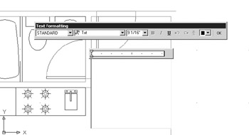
At the Specify opposite corner of [Height/Justify/Line spacing/Rotation/Style/ Width]: prompt, click the second point indicated in the top image in Figure 8.1. The Text Formatting toolbar appears with the Multiline Text Editor superimposed over the area you just selected.
-
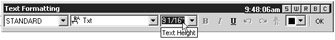
You could start typing the text for the room label, but first you need to select a size. Point to the Text Height drop-down list and click it. The default font size highlights.
-
Enter 6 to make the default height 6 ² . Metric users should enter 15 for a text height of 15 cm.
Tip Why make the text so tall? Remember that you are drawing at full scale, and anything you draw will be reduced in the plotted drawing. Text height is discussed in more detail later in this chapter.
-
Click the text panel and type the word Entry . As you type, the word appears in the text panel, just as it will appear in your drawing. As you will see later, the text also appears in the same font as the final text.
Tip The default font is a native AutoCAD font called Txt.shx . As you will see later, you can also use TrueType fonts and PostScript fonts.
-
Press
to advance one line; then enter 6 ¢ by 7 ¢ . -
Press
to advance another line and enter [182 cm by 213 cm] . -
Press
again to advance another line and enter carpet floor . -
Click OK in the Text Formatting toolbar. The text appears in the drawing just as it did in the text editor (see the bottom image in Figure 8.1).
The Text Formatting toolbar and text editor work like any text editor, so if you make a typing error, you can highlight the error and then retype the letter or word. You can also perform other word processing functions such as search and replace, you can import text, and you can make font changes.
You also saw that the text editor shows you how your text will appear in the location you selected in step 3. If your view of the drawing is such that the text is too small to be legible, the Text Formatting toolbar will enlarge the text so you can read it clearly. Likewise, if you are zoomed in too close to see the entire text, the Text Formatting toolbar will adjust the text in its text editor to enable you to see all the text.
In the next section, you'll look at some of the many options you have available for formatting text.
| Tip | If text is included in an area where a hatch pattern is to be placed, AutoCAD automatically avoids hatching over the text. If you add text over a hatched area, you must rehatch the area to include the text in the hatch boundary. |
EAN: 2147483647
Pages: 261