Working on Layers
Working on Layers
So far you have created layers and then assigned objects to those layers. In this section, you'll learn how to use the Layer drop-down list in the Properties toolbar to assign layers to objects. In the process, you'll make some additions to the drawing.
The current layer is still Layer 0, and unless you change the current layer, every new object you draw will be on Layer 0. Here's how to change the current layer:
-
Click the arrow button next to the layer name on the Properties toolbar. A drop-down list opens, showing you all the layers available in the drawing.
Notice the icons that appear next to the layer names ; these control the status of the layer. You'll learn how to work with these icons later in this chapter. Also notice the box directly to the left of each layer name. This shows you the color of the layer.
Tip Momentarily placing the cursor on an icon in the Layer drop-down list displays a tool tip that describes the icon's purpose.
-
Click the Jamb layer name. The drop-down list closes , and the name Jamb appears in the tool- bar's layer name box. Jamb is now the current layer.
Tip You can also use the Layer command to reset the current layer. To do this here, enter “Layer (be sure to include the minus sign) at the command prompt, and at the ?/Make/Set/New/ON/OFF/Color/Ltype/LWeight/ Plot/PStyle/Freeze/Thaw/LOck/Unlock/stAte]: prompt, enter S for Set. At the Enter layer name to make current or <select object>: prompt, enter Jamb and then press
 twice to exit the Layer command.
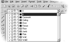
-
Zoom in on the door and draw a 5 ² line; start at the lower-right corner of the door and draw toward the right. Metric users should draw a 13 cm line.
-
Draw a similar line from the top-right end of the arc. Your drawing should look like Figure 4.13.
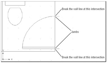
Figure 4.13: Door at wall with door jamb added
Because you assigned the color green to the Jamb layer, the two lines you just drew to represent the door jambs are green. This gives you immediate feedback about what layer you are on as you draw.
Now you will use the part of the wall between the jambs as a line representing the door header (the part of the wall above the door). To do this, you will have to cut the line into three line segments and then change the layer assignment of the segment between the jambs:
-
 In the Modify toolbar, click the Break At Point tool.
 -
At the Select object: prompt, click the wall between the two jambs.
-
At the Specify first break point: prompt, use the Endpoint Osnap override to pick the endpoint of the door's arc that is touching the wall, as shown in Figure 4.13, earlier in this chapter.
-
Click Break on the Modify toolbar, and then repeat steps 2 and 3, this time using the jamb near the door hinge location to locate the break point (see Figure 4.13).
Though it may not be obvious, you've just broken the right-side wall line into three line segments: one at the door opening and two more on either side of the jambs. You can also use the Break tool (next to the Break At Point tool) to produce a gap in a line segment.
| Tip | The Break At Point tool will not work on a circle. You can, however, use the Break tool to place a small gap in the circle. If you create a small enough gap, the circle will still appear as a full circle. |
Next, you'll change the Layer property of the line between the two jambs to the Ceiling layer. But instead of using the Properties tool, as you've done in earlier exercises, you'll use a shortcut method:
-
Click the line between the door jambs to highlight it. Notice that the layer listing in the Properties toolbar changes to Wall. Whenever you select an object to expose its grips, the Layer, Color, Linetype, and Line Width listings in the Properties toolbar change to reflect those properties of the selected object.
-
Click the layer name in the Properties toolbar. The layer drop-down list appears.
-
Click the Ceiling layer. The list closes, and the line you selected changes to the magenta color, showing you that it is now on the Ceiling layer. Also notice that the color list in the Properties toolbar also changes to reflect the new color for the line.
-
Press the Esc key twice to clear the grip selection. Notice that the layer returns to Jamb, the current layer.
-
Click the Zoom Previous tool in the Standard toolbar, or choose View Zoom Previous to return to the previous view.
In this exercise, you saw that by selecting an object with no command active, the object's properties are immediately displayed in the Properties toolbar under the Layer, Color, and Linetype boxes. Using this method, you can also change an object's color, line type, and line width independent of its layer. Just as with the Properties tool, you can select multiple objects and change their layers through the layer drop-down list. These options in the Properties toolbar offer a quick way to edit some of the properties of objects.
Now you'll finish the bathroom by adding a sink to a layer named Casework:
-
Open the Layer Properties Manager dialog box and create a new layer called Casework .
-
 With the Casework layer selected in the layer list, click the Set Current button at the top of the dialog box.
 -
Click the color swatch for the Casework layer listing, and then select Blue from the Select Color dialog box. Click OK to exit the dialog box.
-
Click OK in the Layer Properties Manager dialog box. Notice that the layer listing in the Properties toolbar indicates that the current layer is Casework.
Now you'll add the sink. As you draw, the objects will appear in blue, the color of the Casework layer.
-
Choose View Zoom All.
-
Click the Insert Block tool on the Draw toolbar, and then click the Browse button in the Insert dialog box. This opens the Select Drawing File dialog box.
-
Locate the Sink file and double-click it.
-
In the Insert dialog box, make sure that the Specify On-Screen options in both the Scale and Rotation groups are not selected; then click OK.
-
Place the sink roughly in the upper-right corner of the bathroom plan, and then use the Move command to place it accurately in the corner, as shown in Figure 4.14.
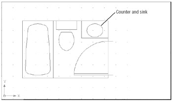
Figure 4.14: Bathroom with sink and countertop added
Controlling Layer Visibility
I mentioned earlier that you'll sometimes want to display only certain layers to work with in a drawing. In this bathroom, there is a door header that would normally appear only in a reflected ceiling plan. To turn off a layer so that it becomes invisible, you click the Off button in the Layer Properties Manager dialog box, as shown in these steps:
-
Open the Layer Properties Manager dialog box by clicking the Layers tool in the Properties toolbar.
-
Click the Ceiling layer in the layer list.
-
Click the lightbulb icon in the layer list, next to the Ceiling layer name. The lightbulb icon changes from yellow to gray to indicate that the layer is off.
-
Click the OK button to exit the Layer Properties Manager dialog box. When you return to the drawing, the header disappears because you have made it invisible by turning off its layer (see Figure 4.15).
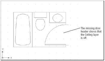
Figure 4.15: Bathroom with Ceiling layer turned off
You can also control layer visibility by using the layer drop-down list on the Object Properties toolbar.
-
On the Object Properties toolbar, click the layer drop-down list.
-
Find the Ceiling layer and notice that its lightbulb icon is gray. This tells you that the layer is off and not visible.
-
Click the lightbulb icon to make it yellow.
-
Now click the drawing area to close the layer drop-down list, and the door header reappears.
Figure 4.16 explains the role of the other icons in the layer drop-down list.
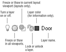
Figure 4.16: The layer drop- down list icons
The missing door header shows that the Ceiling layer is off.
Finding the Layers You Want
With only a handful of layers, it's fairly easy to find the layer you want to turn off. It becomes much more difficult, however, when the number of layers exceeds 20 or 30. The Layer Properties Manager dialog box offers some useful tools to help you find the layers you want fast.
Now suppose you have several layers whose names begin with C, such as C-lights, C-header, and C-pattern, and you want find those layers quickly. You can click the Name button at the top of the layer list to sort the layer names in alphabetic order. (You can click the Name button again to reverse the order.) To select those layers for processing, click the first layer name that starts with C; then scroll down the list until you find the last layer of the group and Shift+click it. All the layers between those layers will be selected. If you want to deselect some of those layers, hold down the Ctrl key while clicking the layer names you don't want to include in your selection. Or Ctrl+click other layer names you do want selected.
The Color and Linetype buttons at the top of the list let you control which layers appear in the list by virtue of their color or line-type assignments. Other buttons sort the list by virtue of the status: On/Off, Freeze/Thaw, Lock/Unlock, and so forth. (See the " Other Layer Options" sidebar later in this chapter.)
Now try changing the layer settings again, turning off all the layers except Wall and Ceiling and leaving just a simple rectangle. In this exercise, you'll get a chance to experiment with the On/Off options of the Layer Properties Manager dialog box:
-
Click the Layers button in the Object Properties toolbar or choose Format Layers.
-
Click the topmost layer name in the list box; then Shift+click the bottommost layer name. All the layer names are highlighted.
Tip Another way to select all the layers at once in the Layer Properties Manager dialog box is to right-click the layer list and then choose the Select All option from the shortcut menu. And if you want to clear your selections, right-click the layer list and choose Clear All.
-
Ctrl+click the Wall and Ceiling layers to deselect them and thus exempt them from your next action.
-
Click the lightbulb icon of any of the highlighted layer names or click the On check box in the Details section of the dialog box to clear the checkmark.
-
A message appears warning you that the current layer will be turned off. Click OK in the message box. The lightbulb icons turn gray to show that the selected layers have been turned off.
-
Click OK. The drawing now appears with only the Wall and Ceiling layers displayed (see Figure 4.17).
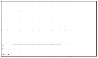
Figure 4.17: The bathroom with all layers except Wall and Ceiling turned off -
Open the Layer Properties Manager dialog box again and select all the layers as you did in steps 2 and 3, and then click the On button or any of the gray lightbulbs to turn on all the layers at once.
-
Click OK to return to the drawing.
In this exercise, you turned off a set of layers with a single click on a lightbulb icon. You can freeze/thaw, lock/unlock, or change the color of a group of layers in a similar manner by clicking the appropriate layer property. For example, clicking a color swatch of one of the selected layers opens the Select Color dialog box, in which you can set the color for all the selected layers.
Taming an Unwieldy List of Layers
Chances are, you will eventually end up with a fairly long list of layers. Managing such a list can become a nightmare, but AutoCAD provides some tools to help you organize layers so that you can keep track of them more easily.
| |
You might have noticed the Freeze and Thaw buttons in the Layer Properties Manager dialog box. These options are similar to the On and Off buttons. However, Freeze not only makes layers invisible; it also tells AutoCAD to ignore the contents of those layers when you use the All response to the Select objects: prompt. Freezing layers can save time when you issue a command that regenerates a complex drawing. This is because AutoCAD ignores objects on frozen layers during Regen. You will get firsthand experience with Freeze and Thaw in Chapter 6.
Another pair of Layer Properties Manager options, Lock and Unlock, offer a function similar to Freeze and Thaw. If you lock a layer, you can view and snap to objects on that layer, but you can't edit those objects. This feature is useful when you are working on a crowded drawing and you don't want to accidentally edit portions of it. You can lock all the layers except those you intend to edit and then proceed to work without fear of making accidental changes.
Three more options ”Lineweight, Plot Style, and Plot ”offer control over the appearance of printer or plotter output. Lineweight lets you control the width of lines in a layer. Plot Style lets you assign plotter configurations to specific layers. (You'll learn more about plot styles in Chapter 7.) Plot lets you determine whether a layer gets printed in hard-copy output. This can be useful for setting up layers you might use for layout purposes only.
Finally, you can save layer settings for later recall by using the Layer State Manager tool in the upper- left corner of the Layer Properties Manager dialog box. This feature is extremely useful when you want to save different layer combinations. The section "Managing Layers" in Chapter 12 shows you how to use this feature. This option is also accessible from the State option in the command-line version of the Layer command.
| |
On the left side of the Layer Properties Manager dialog box, you'll see a set of tools and a list box designed to help you with your layer management tasks .
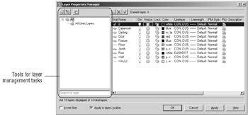
In the upper-left corner of the dialog box, you see a toolbar with three tools:
The New Property Filter tool lets you filter your list of layers to display only layers with certain properties, such as specific colors or names.
The New Group Filter tool lets you create named groups of layers that can be quickly recalled at any time. This tool is helpful if you often work with specific sets of layers. For example, you might have a set of layers in an architectural drawing that pertains to the electrical layout. You could create a group filter called Electrical that filters out all layers except those pertaining to the electrical layout. The filters don't affect the layers in any way; they just limit which layers are displayed in the main layer list.
The Layer State Manager tool lets you create sets of layer states. For example, if you want save the layer settings that have only the wall and door layer turned on, you can do so by using this tool.
Filtering Layers by Their Properties
Below these three tools is a filter list, which is a hierarchical list displaying the different sets of layer properties and group filters. Right now, you don't have any filters in place so you see only the All and All Used Layers.
In this section, you'll learn how the tools and the filter list box work. You'll start with a look at the New Property Filter tool:
-
Open the Layer Properties Manager dialog box by clicking the Layer tool in the Properties toolbar. You can also select Format Layer from the toolbar.
-
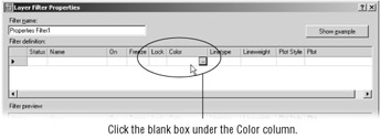
 Click the New Property Filter tool in the upper-left corner of the dialog box. The Layer Filter Properties dialog box appears. You see two list boxes. The Filter Definition list box at the top is where you enter your filter criteria. The Filter Preview list box below is a preview of your layer list based on the filter options. Right now, there are no filter options so the Filter Preview list shows all the layers.
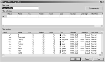
-
In the Filter Definition list box, click the blank box just below the Color label. A button appears in the box.
-
Click in the blank box again; then enter red
. The Filter Preview changes to show only layers that are red. In the current drawing, there is only one layer that has been assigned the color red. -
Click twice in the blank box just below the one you just edited. Again you see a button appear.
-
This time, enter green
. Now the layers that are green appear in the Filter Preview list. Tip You can also select a color from the Select Color dialog box by clicking the button that appears in the box.
-
In the Filter Definition list, click in the Name column in the third row down. Notice that a cursor appears followed by an asterisk.
-
Enter F
. Now you see two new layers added to the Filter Preview list that have names beginning with F. -
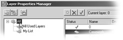
In the Filter Name text box at the upper-left corner of the dialog box, change the name Properties Filter 1 to My List Then click OK. Now you see the My List filter in the list box on the left side of the Layer Properties Manager.
The layer list shows only the layers that have properties conforming to those you selected in the Layer Filter Properties dialog box. Notice that My List is highlighted in the filter list to the left. This tells you that My List is the current layer property filter being applied to the layer list to the right.
You can change the layer list display by selecting different options in the filter list. Try these steps:
-
Click the All option in the filter list at the left side of the dialog box. The layer list to the right changes to display all the layers in the drawing. Also note that a brief description of the current layer filter is displayed at the bottom of the dialog box.
-
Click the All Used Layers option in the filter list. Now only layers that contain objects are displayed.
-
Click My List. The layer list changes back to the limited set of layers from your filter list.
-
Double-click My List. The Layer Filter Properties dialog box opens and displays the list of layer properties you set up earlier for My List. You can edit the criteria for your filter by making modifications in this dialog box.
-
Click Cancel to exit the Layer Filter Properties dialog box.
Creating Layer Groups
The preceding exercise shows how you can filter out layer names based on the properties you specify in the Layer Filter Properties dialog box. But suppose you want to create a layer filter list by graphically selecting objects on the screen. You can use the New Group Filter tool to do just that:
-
 Click the New Group Filter tool in the upper-left corner of the Layer Properties Manager dialog box. You see a new listing appear called Group Filter1.
 -
Right-click the Group Filter1 listing and then choose Select Layers Add from the shortcut menu. The Layer Properties Manager dialog box temporarily closes to enable you to select objects in your drawing. Notice that your cursor is now an Object Selection cursor.
-
Click on a line representing a wall of the bathroom; then click on the door. Press
when you are finished with your selection. The Layer Properties Manager dialog box reappears and now you see the layers of the two objects you selected displayed in the layer list. Also note that Group Filter1 is highlighted in the filter list to the left. 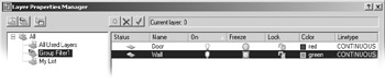
Tip You might have noticed the Select Layers Replace option in the shortcut menu in step 2. This option lets you completely replace an existing group filter with a new selection set. It works just like the Select Layers Add option.
Earlier, you saw how you can double-click on a properties filter to edit a properties filter list. But group filters work in a slightly different way. If you want to add layers to your group filter, you can click and drag them from the layer list to the group filter name. Here's how it's done:
-
In the Layer Properties Manager dialog box, select All from the filter list to the left.
-
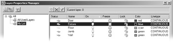
Click the Fixture layer in the layer list; then Ctrl+click the Jamb layer in the list. These are layers you'll add to the Group Filter1 layer group.
-
Click and drag the Fixture layer to the Group Filter1 listing in the filter list to the left.
-
To check the addition to the Group Filter1, click it in the filter list. The Fixture and Jamb layers have been added to the Group Filter1 list.
If you want to delete a layer from a group filter, you can use the shortcut menu, as shown in these steps:
-
With the Group Filter1 list selected, select the Jamb layer from the layer list, and then right- click it.
-
Select Remove From Group Filter in the shortcut menu (make sure you do not select Delete layer). Jamb is removed from the Group Filter1 list.
Tip You can also convert a layer property filter into a group filter. Select the layer property filter from the filter list, right- click, and then select Convert To Group Filter. The icon for the layer property filter will change to a group filter icon, indicating that it is now a group filter.
You've seen how you can add property and group filters to the Layer Properties Manager dialog box by using the tools on the left side of the dialog box. One tool you haven't explored yet is the Layer State Manager. To understand how this tool works, you'll need to learn a little more about AutoCAD, so look for a discussion of the Layer State Manager in Chapter 12 in the section "Managing Layers."
Before you move on, you'll want to know about the options just below the filter list.
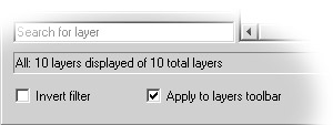
The Invert Filter check box changes the list of layers to show all layers excluding those in the selected filter. For example, If the My List filter contains layers that are red, and you select Invert Filter, the layer list will display all layers except those that are red.
The Apply To Layers Toolbar check box, when selected, will apply the selected filter to the layer drop-down list found in the Properties toolbar.
A text box directly below the filter list enables you to enter portions of a layer name to apply additional filters to the layer list currently displayed. For example, you can enter F* in the text box to display only layers from the current list that have names beginning with F. In this example, the text box contains the words Search for Layer.
Naming Layers To Stay Organized
A-FP-WALL-JAMB
A-RP-WIND-JAMB
A-FP-WIND-SILL
A-CP-WIND-HEAD
A-CP-DOOR-HEAD
L-FP-CURB
C-FP-ELEV
The first character in the layer name designates the discipline related to that layer: A for architectural, L for landscape, C for civil, and so on. In this example, layers with names containing the two characters FP signify floor-plan layers. CP designates ceiling-plan information.
| Tip | These layer examples are loosely based on a layer-naming convention devised by the American Institute of Architects (AIA). As you can see from this example, careful naming of layers can help you manage them. |
If you want to isolate only those layers that have to do with floor plans, regardless of their discipline, enter ??FP* in the Name column of the Layer Filter Properties dialog box. You can then give this layer property filter the name Floor Plan by entering Floor Plan in the Filter Name text box.
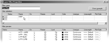
After you've created the Floor Plan layer properties list, you can then pick Floor Plan from the filter list on the right side of the Layer Properties Manager dialog box, and only those layers with names containing the letters FP as their third and fourth characters will appear in the list of layers. You can turn all these layers off, change their color assignment, or change other settings quickly, without having to wade through layers you don't want to touch. You can further create other filter properties to isolate other groups of layers. AutoCAD keeps these filter lists for future use until you delete them by using the Delete option in the shortcut menu (right-click the name of the properties filter and select Delete). In the ??FP* example, the question marks (??) tell AutoCAD that the first two characters in the layer name can be anything. The FP tells AutoCAD that the layer name must contain F and P in these two places of the name. The asterisk (*) at the end tells AutoCAD that the remaining characters can be anything. The question marks and asterisk are known as wildcard characters. They are commonly used filtering tools for both the Unix and Windows operating systems.
As the number of layers in a drawing grows, you will find layer filters to be an indispensable tool. But bear in mind that the successful use of the layer filters can depend on a careful layer-naming convention. If you are producing architectural plans, you might want to consider the AIA layering guidelines.
| Tip | Check out Chapter 19 for some additional tools that will help you manage layer settings. |
Assigning Line Types to Layers
You will often want to use different line types to show hidden lines, center lines, fence lines, or other noncontinuous lines. You can assign a color and a line type to a layer. You then see ISO and complex line types, including lines that can be used to illustrate gas and water lines in civil work, or batt insulation in a wall cavity .
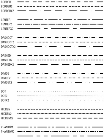
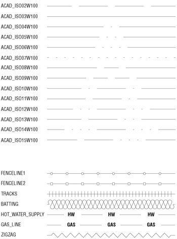
Figure 4.18: Standard , ISO, and complex AutoCAD line types
| Warning | Line types that contain text, such as the gas line sample at the bottom of Figure 4.18, use the current text height and font to determine the size and appearance of the text displayed in the line. A text height of zero displays the text properly in most cases. See Chapter 8 for more on text styles. |
AutoCAD stores line-type descriptions in an external file named Acad.lin , or Acadiso.lin for metric users. You can edit this file in a word processor to create new line types or to modify existing ones. You will see how this is done in Chapter 20.
Adding a Line Type to a Drawing
To see how line types work, add a dash-dot line in the bathroom plan to indicate a shower curtain rod:
-
Open the Layers Properties Manager dialog box and then select All from the filter list.
-
Click New and then type Pole to create a new layer called Pole.
Tip If you are in a hurry, you can simultaneously load a line type and assign it to a layer by using the Layer command. In this exercise, you would enter “Layer
at the command prompt. Then enter L , dashdot , pole , and press to exit the Layer command. -
In the Pole layer listing, under the Linetype column, click the word Continuous to open the Select Linetype dialog box. To find the Linetype column, you might need to scroll the list to the right by using the scroll bar at the bottom of the list.
Warning The word "Continuous" will truncate to "Cont uous" when the Linetype column is at its default width and the Continuous option is selected.
-
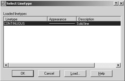
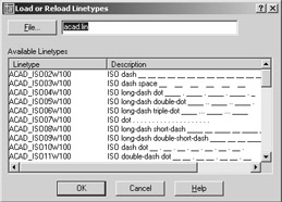
The Select Linetype dialog box offers a list of line types to choose from. In a new file such as the Bath file, only one line type is available by default. You must load any additional line type you want to use. Click the Load button at the bottom of the dialog box to open the Load Or Reload Linetypes dialog box. Notice that the list of line-type names is similar to the layer drop-down list. You can sort the names alphabetically or by description by clicking the Line- type or Description headings at the top of the list.
-
In the Available Linetypes list, scroll down to locate the dash-dot line type, click it, and then click OK.
-
Notice that the Dashdot line type is now added to the line types available in the Select Line- type dialog box.
-
Click Dashdot to highlight it; then click OK. Now Dashdot appears in the Pole layer listing under Linetype.
-
With the Pole layer still highlighted, click the Current button to make the Pole layer current.
-
Click OK to exit the Load Or Reload Linetypes dialog box.
-
Turn off the Running Osnap mode; then draw a line across the opening of the tub area, from coordinate 4'-4 ² ,1'-10 ² to coordinate 4'-4 ² ,6'-10 ² . Metric users should draw a line from coordinate 133,56 to 133,208.
Controlling Line-Type Scale
Although you have designated this as a dash-dot line, it appears solid. Zoom in to a small part of the line, and you'll see that the line is indeed as you specified.
Because you are working at a scale of 1 ² = 1', you must adjust the scale of your line types accordingly . This, too, is accomplished in the Layer Properties Manager dialog box. Here are the steps:
-
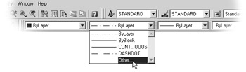
Choose Format Linetype from the pull-down menu. You can also select Other from the Linetype drop-down list in the Properties toolbar.
-
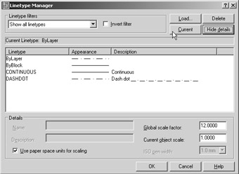
The Linetype Manager dialog box appears. Click the Show Details button in the upper-right corner of the dialog box. You'll see some additional options appear at the bottom.
Tip The Linetype Manager dialog box offers the Load and Delete buttons that let you load or delete a line type directly without having to go through a particular layer's line-type setting.
-
Double-click the Global Scale Factor text box and then type 12 (metric users type 30 ). This is the scale conversion factor for a 1 ² = 1' scale (see Chapter 3).
-
Click OK. The drawing regenerates, and the shower curtain rod is displayed in the line type and at the scale you designated.
-
Click the Zoom Previous tool so your drawing looks like Figure 4.19.
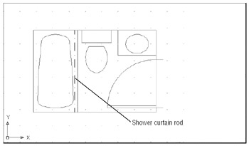
Figure 4.19: The completed bathroomTip You can also use the Ltscale system variable to set the line-type scale. Type Ltscale
, and at the LTSCALE New scale factor <1.0000>: prompt, enter 12 . Tip If you change the line type of a layer or object, but the object remains a continuous line, check the Ltscale system variable. It should be set to your drawing scale factor. If this doesn't work, set the Viewres system variable to a higher value (see Chapter 6). (Viewres can also be set by the Arc And Circle Smoothness option in the Display tab of the Options dialog box.) The behavior of line-type scales depends on whether you are in Model Space or in a drawing layout. If your efforts to control line-type scale have no effect on your line type's visibility, you might be in a drawing layout. See Chapter 12 for more on Model Space and layouts.
Remember that if you assign a line type to a layer, everything you draw on that layer will be of that line type. This includes arcs, polylines, circles, and traces. As explained in the " Setting Individual Colors, Line Types, and Line-Type Scales" sidebar later in this section, you can also assign different colors and line types to individual objects, rather than relying on their layer assignment to define color and line type. However, you might want to avoid assigning colors and line types directly to objects until you have some experience with AutoCAD and a good grasp of your drawing's organization.
In the previous exercise, you changed the global line-type scale setting. This affects all noncontinuous line types within the current drawing. You can also change the line-type scale of individual objects by using the Properties button on the Object Properties toolbar. Or you can set the default line-type scale for all new objects, with the Current Object Scale option in the Linetype Manager dialog box.
When individual objects are assigned a line-type scale, they are still affected by the global line- type scale set by the Ltscale system variable. For example, say you assign a line-type scale of 2 to the curtain rod in the previous example. This scale is then multiplied by the global line-type scale of 12, for a final line-type scale of 48.
| Tip | You can also set the default line-type scale setting for individual objects by using the Celtscale system variable. After it is set, only newly created objects are affected. You must use the Properties tool to change the line-type scale of individual existing objects. |
If the objects you draw appear in a different line type from that of the layer they are on, check the default line type by using the Linetype Control drop-down list on the Object Properties toolbar. You can also choose Format Linetype. Then, in the Linetype Manager dialog box, highlight ByLayer in the Linetype list, and then click the Current button. In addition, check the line-type scale of the object itself, by using the Properties palette. A different line-type scale can make a line appear to have an assigned line type that might not be what you expect. (See the sidebar " Setting Individual Colors, Line Types, and Line-Type Scales.")
Adding the Final Detail
If you are working through the tutorial, your final task here is to set up an insertion point for the current drawing, to facilitate its insertion into other drawings in the future. Follow these steps:
-
Type Base
. -
At the Enter base point <0 '-0 ² ,0'-0 ² ,0'-0 ² >: prompt, pick the upper-left corner of the bathroom. The bathroom drawing is now complete.
-
Choose File Save to record your work up to now.
Controlling Line Weights
You might have noticed an option in the Layer Properties Manager dialog box called Lineweight. This option lets you control the thickness of your lines by adjusting the Lineweight setting, either through layer assignments or through direct object property assignment. This setting lets you view line weights as they will appear in your final plot.
With the Lineweight option, you have greater control over the look of your drawings. This can save time because you don't have to print your drawing just to check for line weights. You'll be able to see how thick or thin your lines are as you edit your drawing. You'll get a chance to delve into line weights in Chapter 7.
| |
If you prefer, you can set up AutoCAD to assign specific colors and line types to objects, instead of having objects take on the color and line-type settings of the layer on which they reside. Normally, objects are given a default color and line type called ByLayer, which means each object takes on the color or line type of its assigned layer. (You've probably noticed the word ByLayer in the Object Properties toolbar and in various dialog boxes.)
Use the Properties tool on the Object Properties toolbar to change the color or line type of existing objects. This tool opens a dialog box that lets you set the properties of individual objects. For new objects, use the Color tool on the Object Properties toolbar to set the current default color to red (for example), instead of ByLayer. The Color tool opens the Select Color dialog box, in which you select your color from a toolbar. Then everything you draw will be red, regardless of the current layer color.
For line types, you can use the Linetype drop-down list in the Object Properties toolbar to select a default line type for all new objects. The list shows only line types that have already been loaded into the drawing, so you must first load a line type before you can select it.
Another possible color and line-type assignment is ByBlock, which you also set with the Properties button. ByBlock makes everything you draw white, until you turn your drawing into a block and then insert the block on a layer with an assigned color. The objects then take on the color of that layer. This behavior is similar to that of objects drawn on Layer 0. The ByBlock line type works similarly to the ByBlock color.
Finally, if you want to set the line-type scale for each individual object, instead of relying on the global line- type scale (the Ltscale system variable), you can use the Properties button to modify the line-type scale of individual objects. Or you can use the Object Creation Modes dialog box (via the Object Creation button in the Object Properties toolbar) to set the line-type scale to be applied to new objects. In place of using the Properties button, you can set the Celtscale system variable to the line-type scale you want for new objects.
As mentioned earlier, you should stay away from assigning colors and line types to individual objects until you are comfortable with AutoCAD; and even then, use color and line-type assignments carefully. Other users who work on your drawing might have difficulty understanding your drawing's organization if you assign color and line-type properties indiscriminately.
| |
EAN: 2147483647
Pages: 261