Organizing Information with Layers
Organizing Information with Layers
Another tool for organization is the layer. Layers are like overlays on which you keep various types of information (see Figure 4.12). In a floor plan of a building, for example, you want to keep the walls, ceiling, plumbing fixtures, wiring, and furniture separate so that you can display or plot them individually or combine them in different ways. It's also a good idea to keep notes and reference symbols about each element of the drawing, as well as the drawing's dimensions, on their own layers. As your drawing becomes more complex, you can turn the various layers on and off to allow easier display and modification.
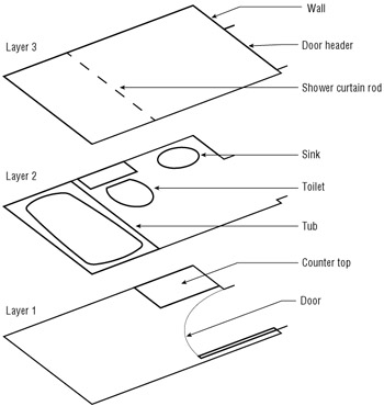
Figure 4.12: Placing drawing elements on separate layers
For example, one of your consultants might need a plot of just the dimensions and walls, without all the other information; another consultant might need only a furniture layout. Using manual drafting, you would have to redraw your plan for each consultant or use overlay drafting techniques, which can be cumbersome. With AutoCAD, you can turn off the layers you don't need and plot a drawing containing only the required information. A carefully planned layering scheme helps you produce a document that combines the different types of information needed in each case.
Using layers also enables you to modify your drawings more easily. For example, suppose you have an architectural drawing with separate layers for the walls, the ceiling plan, and the floor plan. If any change occurs in the wall locations, you can turn on the ceiling plan layer to see where the new wall locations will affect the ceiling and then make the proper adjustments.
AutoCAD allows an unlimited number of layers, and you can name each layer anything you want.
Creating and Assigning Layers
You'll start your exploration of layers by using a dialog box to create a new layer, giving it a name and assigning a color . Then you'll look at alternate ways of creating a layer through the command line. Then you'll assign the new layer to the objects in your drawing. Start by getting familiar with the Layer Properties Manager dialog box.
-
On the CD Open the Bath file you created earlier in this chapter. (If you didn't create one, use the file 04b-bath.dwg or 04b-bath-metric.dwg from the companion CD.)
-
To display the Layer Properties Manager dialog box, click the Layer Properties Manager tool in the Properties toolbar, or choose Format Layer from the pull-down menu. You can also type LA
 to use the keyboard shortcut.
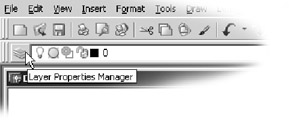
Tip The Layer Properties Manager dialog box shows you at a glance the status of your layers. Right now, you have only one layer, but as your work expands, so will the number of layers. You will then find this dialog box indispensable .
-
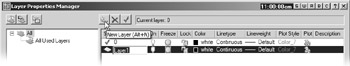
Click the New Layer button at the top of the dialog box. The button has an icon that looks like a star next to a sheet.
A new layer named Layer1 appears in the list box. Notice that the name is highlighted. This tells you that by typing you can change the default name to something better suited to your needs.
-
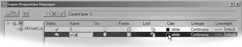
Type Wall . As you type, your entry replaces the Layer1 name in the list box.
-
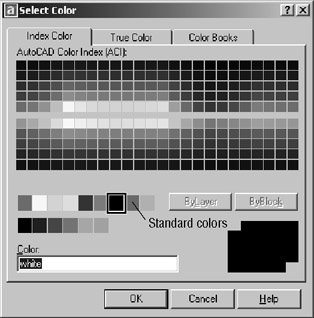
With the Wall layer name highlighted, click the Color icon in the Wall layer listing to display a listing of colors that you can assign to the Wall layer. The Color icon can be found under the Color column and currently shows White as its value. The Icon is just to the left of the word "white".
The Select Color dialog box appears.
-
In the row of Standard Colors next to the ByLayer button, click the green square and then click OK. Notice that the color swatch in the Wall layer listing is now green. (You could have just chosen Green from the Colors drop-down list, but by using the Select Color dialog box you can see that many other colors are available.)
-
When the Layer Properties Manager dialog box returns, click OK to close it.
From this point on, any object assigned to the Wall layer will appear green unless the object is specifically assigned a different color.
Using True or Pantone Colors
ACAD only In the preceding exercise, you chose a color from the Index Color tab of the Select Color dialog box. Most of the time, you'll find that the Index Color tab offers enough colors to suit your needs. But if you are creating a presentation drawing in which color selection is important, you can choose colors from either the True Color or the Color Books tab of the Select Color dialog box.
The True Color tab offers a full range of colors through a color palette similar to one found in Adobe Photoshop and other image-editing programs.
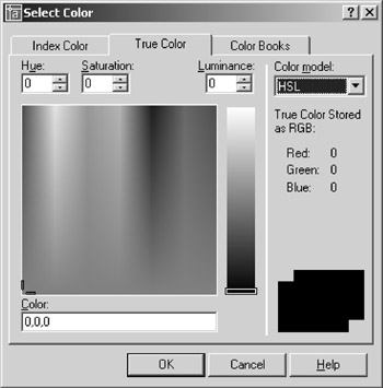
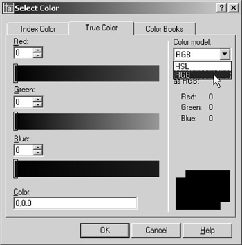
You have the choice of using hue, saturation, and luminance, which is the HSL color model, or you can use the RGB (red, green, blue) color model. You can select HSL or RGB from the Color Model drop-down list in the upper-right corner of the dialog box.
| |
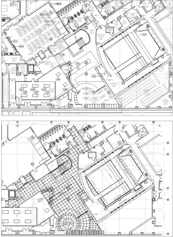
Layering enables you to use a single AutoCAD drawing for multiple purposes. A single drawing can show both the general layout of the plan and more detailed information such as equipment layout or floor-paving layout.
The following two images are reproductions of the San Francisco Main Library's lower level, which show how one floor plan file was used for two purposes. The first view shows the layout of furnishings, and the second view shows a paving layout. In each case, the same floor plan file was used, but in the first panel, the paving information is on a layer that is turned off. Layers also facilitate the use of differing scales in the same drawing. Frequently, a small-scale drawing of an overall plan will contain the same data for an enlarged view of other portions of the plan, such as a stairwell or an elevator core . The detailed information, such as notes and dimensions, might be on a layer that is turned off for the overall plan.
| |
If you installed the PANTONE color option when you installed AutoCAD, you can also select from a PANTONE "color book" by using the Color Books tab. The color book option enables you to match colors to a PANTONE color book for offset printing.
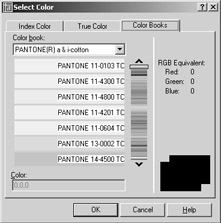
| Tip | The Files tab of the Options dialog box (choose Tools Options) contains the Color Book Location option, which tells AutoCAD where to look for the Color Book settings. |
Now let's continue with our look at layers in AutoCAD.
Understanding the Layer Properties Manager Dialog Box
The Layer Properties Manager dialog box conforms to the Windows interface standard. The most prominent feature of this dialog box is the layer list box, as you saw in the preceding exercise. Notice that the bar at the top of the list of layers offers several buttons for the various layer properties. Just as you can adjust Windows Explorer, you can adjust the width of each column in the list of layers by clicking and dragging either side of the column head buttons . You can also sort the layer list based on a property simply by clicking the property name at the top of the list. And, just as with other Windows list boxes, you can Shift+click names to select a block of layer names, or you can Ctrl+click individual names to select multiples that do not appear together. These features will become helpful as your list of layers enlarges.
Above the layer list, you'll see a box displaying the current layer. Just to the left of the current layer name are three tool buttons.
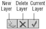
You've already seen how the New Layer tool works. That's the tool that has a star and sheet icon. The tool with the X icon is the Delete Layer tool. You select a layer or group of layers and click this button to delete layers. Be aware that you cannot delete layer 0, locked layers, or layers that contain objects. The tool with the checkmark icon is the Current Layer tool. It enables you to set the current layer on which you want to work. You can also see at a glance which layer is the current one by the green checkmark under the Status column of the layer list.
| Tip | Another way to create or delete layers is to select a layer or set of layers from the list box and then right-click. A menu appears offering the same functions as the tools above the layer list. |
You'll also notice another set of three tools farther to the left of the Layer Properties Manager dialog box. Those tools offer features to organize your layers in a meaningful way. You'll get a closer look at those tools a little later in this chapter.
Controlling Layers through the Layer Command
You have seen how the Layer Properties Manager dialog box makes it easy to view and edit layer information and how you can easily select layer colors from an on-screen toolbar. But you can also control layers through the command prompt.
| Warning | LT users will not see the Pstyle option in the Layer prompt or the Truecolor/Colorbook options in the Color option prompt. |
Use these steps to control layers through the command prompt:
-
First, press the Esc key to make sure any current command is canceled .
-
At the command prompt, enter “Layer
. Make sure you include the minus sign in front of the word Layer . The following prompt appears: Enter an option [?/Make/Set/New/ON/OFF/Color/Ltype/LWeight/Plot/PStyle/Freeze/Thaw/LOck/ Unlock/stAte]:
You'll learn about many of the options in this prompt as you work through this chapter.
-
Enter N
to select the New option. -
At the Enter name list for new layer(s): prompt, enter Wall2
. The [?/Make/Set/New/ ON/ OFF/Color/Ltype/LWeight/Plot/PStyle/Freeze/Thaw/LOck/Unlock /stAte]: prompt appears again. -
Enter C
. -
At the New color [Truecolor/Colorbook] <7 (white)>: prompt, enter Yellow
. Or you can enter 2 , the numeric equivalent of the color yellow in AutoCAD. -
At the Enter name list of layer(s) for color 2 (yellow) <0>: prompt, enter Wall2
. The [?/Make/Set/New/ON/OFF/Color/Ltype /LWeight/ Plot/Pstyle/Freeze/Thaw/LOck/Unlock/stAte]: prompt appears again. -
Press
to exit the Layer command.
Each method of controlling layers has its own advantages. The Layer Properties Manager dialog box offers more information about your layers at a glance. On the other hand, the Layer command offers a quick way to control and create layers if you're in a hurry. Also, if you intend to write custom macros, you will want to know how to use the Layer command as opposed to using the Layer Properties Manager dialog box, because dialog boxes cannot be controlled through custom toolbar buttons or scripts.
| Tip | Another advantage of using the keyboard commands is that you can recall previously entered keystrokes by using the Up and Down arrow keys. For example, to recall the layer named Wall2 you entered in step 4 in the previous exercise, press the Up arrow key until Wall2 appears in the prompt. This saves time when you are performing repetitive operations such as creating multiple layers. This feature does not work with tools selected from the toolbars . |
Assigning Layers to Objects
When you create an object, that object is assigned to the current layer. Until now, only one layer has existed ”Layer0 ”which contains all the objects you've drawn so far. Now that you've created some new layers, you can reassign objects to them by using the Properties palette:
-
Select the four lines that represent the bathroom walls. If you have problems singling out the wall to the left, use a window to select the wall line.
-
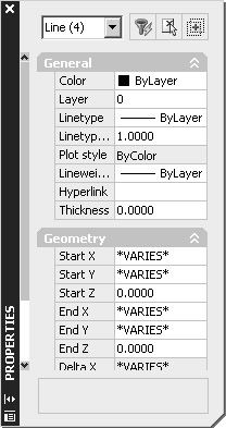
With the cursor in the drawing area, right-click and choose Properties from the shortcut menu to open the Properties palette. This palette lets you modify the properties of an object or set of objects. (See the upcoming " Understanding Object Properties" sidebar for more on the properties of objects.)
-
Click the Layer option from the listing in the Properties palette. Notice that an arrow appears in the layer name to the right of the Layer option.
-
Click the downward-pointing arrow to the far right of the Layer option to display a list of all the available layers.
-
Select the Wall layer from the list. Notice that the wall lines you selected change to a green color. This tells you that that the objects have been assigned to the Wall layer. Remember that you assigned a green color to the Wall layer.
-
Close the Properties palette by clicking the X button in the upper-left corner.
The bathroom walls are now on the new layer called Wall, and the walls are changed to green. Layers are more easily distinguished from one another when you use colors to set them apart.
Next, you will practice the commands you learned in this section and try out some new ones by creating some new layers and changing the layer assignments of the rest of the objects in your bathroom:
-
Open the Layer Properties Manager dialog box (choose Format Layers or click the Layers button in the Properties toolbar). Create a new layer called Fixture and give it the color blue.
Tip You can change the name of a layer by clicking it in the Layer Properties Manager dialog box. After it is highlighted, click it again so that a box surrounds the name. You can then rename the layer. This works in the same way as renaming a file or folder in Windows.
-
Click the Tub and Toilet blocks, and then right-click and choose Properties from the shortcut menu to open the Properties palette.
-
Click Layer in the list of properties, and then select Fixture from the drop-down layer list to the right of the Layer listing.
-
Click the X in the top corner of the Properties palette to dismiss it, and then press the Esc key to clear your selection.
-
Now create a new layer for the door, name the layer Door , and make it red.

Understanding Object Properties It helps to think of the components of an AutoCAD drawing as having properties. For example, a line has geometric properties, such as the length, and coordinates that define its endpoints. An arc has a radius, a center, and beginning and ending coordinates. And even though a layer is not an object you can grasp and manipulate, it can have properties such as color, line types, and line weight.
By default, objects take on the color, line type, and weight of the layer to which they are assigned, but you can also assign these properties directly to individual objects. These general properties can be manipulated through both the Properties palette and the Properties toolbar.
Although many of the options in the Properties palette might seem cryptic to you, don't worry about them at this point. As you work with AutoCAD, these properties will become more familiar. You'll find that you really won't be too concerned with the geometric properties, because you'll be manipulating those through the standard editing tools in the Modify toolbar. The other properties will be explained in the rest of this chapter and in other chapters.
Tip Within a block, you can change the color assignment and line type of only those objects that are on Layer0. See the sidebar " Controlling Colors and Line Types of Blocked Objects" later in this chapter.
-
Just as you have done with the walls and fixtures, use the Properties palette to assign the door to the Door layer.
-
Use the Layer Properties Manager dialog box to create three more layers for the ceiling, door jambs, and floor, as shown in Table 4.1. Remember that you can open the Select Color dialog box by clicking the color swatch of the layer listing.
In step 3 of the previous exercise, you used the Properties palette, which offered several options for modifying the block. The options displayed in the Properties palette depend on the objects you have selected. With only one object selected, AutoCAD displays options that apply specifically to that object. With several objects selected, you'll see a more limited set of options because AutoCAD can change only those properties that are common to all the objects selected.
| Layer Name | Layer Color (Number) |
|---|---|
| Ceiling | Magenta (6) |
| Jamb | Green (3) |
| Floor | Cyan (4) |
| |
Layer 0 has special importance to blocks. When objects assigned to Layer 0 are used as parts of a block, and that block is inserted on another layer, those objects take on the characteristics of their new layer. On the other hand, if those objects are on a layer other than Layer 0, they maintain their original layer characteristics even if you insert or change that block to another layer. For example, suppose the tub is drawn on the Door layer, instead of on Layer 0. If you turn the tub into a block and insert it on the Fixture layer, the objects the tub is composed of will maintain their assignment to the Door layer, although the Tub block is assigned to the Fixture layer.
It might help to think of the block function as a clear plastic bag that holds together the objects that make up the tub. The objects inside the bag maintain their assignment to the Door layer even while the bag itself is assigned to the Fixture layer. This might be a bit confusing at first, but it should become clearer after using blocks for a while.
AutoCAD also enables you to have more than one color or line type on a layer. For example, you can use the Color and Linetype buttons in the Change Properties palette (the Object Properties button on the Standard toolbar) to alter the color or line type of an object on Layer 0. That object then maintains its assigned color and line type ”no matter what its layer assignment. Likewise, objects specifically assigned a color or line type are not affected by their inclusion into blocks.
| |
EAN: 2147483647
Pages: 261