Grouping Objects
ACAD only Blocks are extremely useful tools, but for some situations, they are too restricting. At times, you will want to group objects so they are connected yet can still be edited individually.
For example, consider a space planner who has to place workstations in a floor plan. Though each workstation is basically the same, some slight variations in each station could make the use of blocks unwieldy. For instance, one workstation might need a different configuration to accommodate special equipment, and another workstation might need to be slightly larger than the standard size . Using a block, you would need to create a block for one workstation, and then for each variation, explode the block, edit it, and then create a new block. A better way is to draw a prototype workstation and then turn it into a group. You can copy the group into position and then edit it for each individual situation, without losing its identity as a group. AutoCAD LT offers a different method for grouping objects. If you are using LT, skip this exercise and continue with the following section, " Grouping Objects for LT Users."
On the CD The following exercise demonstrate how grouping works:
-
Open the drawing named Office1.dwg from the companion CD. Metric users should open Office1-metric.dwg .
-
Use the Zoom command to enlarge just the view of the workstation, as shown in the first image in Figure 4.8.
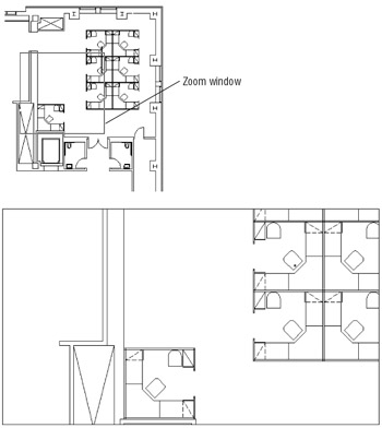
Figure 4.8: A workstation in an office plan -
Type G
 or Group to open the Object Grouping dialog box.
-
Type Station1. As you type, your entry appears in the Group Name text box.
-
Click New in the Create Group group, about midway in the dialog box. The Object Grouping dialog box temporarily disappears to enable you to select objects for your new group.
-
At the Select objects: prompt, window the entire workstation in the lower-left corner of the plan and press
to display the Object Grouping dialog box. Notice that the name Station1 appears in the Group Name box at the top of the dialog box. -
Click OK. You have just created a group.
Now, whenever you want to select the workstation, you can click any part of it to select the entire group. At the same time, you can still modify individual parts of the group ”the desk, partition, and so on ”without losing the grouping of objects.
Grouping Objects for LT Users
LT users will have to use a slightly different method to create a group. If you are using AutoCAD 2005 LT, do the following:
-
LT only Open the drawing named Office1.dwg from the companion CD. Metric users should open Office1-metric.dwg .
-
Use the Zoom command to enlarge just the view of the workstation, as shown in the first image in Figure 4.8.
-
Type G
or Group to open the Group Manager dialog box. 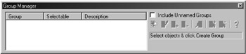
-
Move the dialog box so that you have a clear view of the workstation; then use a selection window to select all the objects of the workstation. You can also click the individual objects of the workstation to make the selection.
-
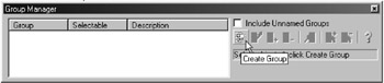
In the Group Manager dialog box, click the Create Group button. A new listing appears in the Group Manager list box.
-
Type Station1
in the text box that appears in the group list. -
Close the Group Manager dialog box.
Now, whenever you want to select the workstation, you can click any part of it to select the entire group. At the same time, you can still modify individual parts of the group ”the desk, partition, and so on ”without losing the grouping of objects.
Modifying Members of a Group
Next, you will make copies of the original group and modify the copies. Figure 4.9 is a sketch of the proposed layout that uses the new workstations. Look carefully , and you'll see that some of the workstations in the sketch are missing a few of the standard components that exist in the Station1 group. One pair of stations has a partition removed; another station has no desk.
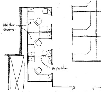
Figure 4.9: A sketch of the new office layout
The exercises in this section show you how to complete your drawing to reflect the design requirements of the sketch.
Start by making a copy of the workstation:
-
Click Copy on the Modify toolbar or type Co
, and click the Station1 group you just created. Notice that you can click any part of the station to select the entire station. If only a single object is selected, press Shift+Ctrl+A and try clicking another part of the group. -
Press
to finish your selection. -
At the Specify base point or displacement: prompt, enter @
. Then enter @8 ' 2 ² <90 to copy the workstation 8 ² feet-, 2 ² inches vertically. Metric users should enter @249<90 . Press to exit the Copy command. Tip In step 3, you can also use the Direct Distance method by typing @
and then pointing the rubber-banding line 90 ° and typing 8 ' 2 ² Metric users should type 249 . -
Issue the Copy command again, but this time click the copy of the workstation you just created. Notice that it, too, is a group.
-
Copy this workstation 8'-2 ² (249 cm for the metric users) vertically, just as you did the original workstation. Press
to exit the Copy command
Next, you'll use grips to mirror the first workstation copy:
-
Click the middle workstation to highlight it, and notice that grips appear for all the entities in the group.
-
Click the grip in the middle-left side, as shown in Figure 4.10.
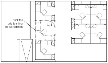
Figure 4.10: Mirroring the new group by using grips -
Right-click the mouse and choose Mirror from the shortcut menu. Notice that a temporary mirror image of the workstation follows the movement of your cursor.
-
Turn on the Ortho mode and pick a point directly to the right of the hot grip you picked in step 2. The workstation is mirrored to a new orientation.
-
Press the Esc key twice to clear the grip selection. Also, turn off the Ortho mode.
Now that you've got the workstations laid out, you need to remove some of the partitions between the new workstations. If you had used blocks for the workstations, you would first need to explode the workstations that have partitions you want to edit. Groups, however, let you make changes without undoing their grouping.
Use these steps to remove the partitions:
-
At the command prompt, press Shift+Ctrl+A. You should see the <Group off> message in the command line. If you see the <Group on> message instead, press Shift+Ctrl+A until you see <Group off> . This turns off groupings so you can select and edit individual objects within a group.
-
Using a window, erase the short partition that divides the two copies of the workstations, as shown in Figure 4.11.
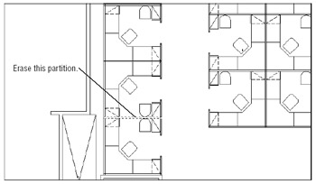
Figure 4.11: Remove the partitions between the two workstations. -
Press Shift+Ctrl+A again to turn groupings back on.
-
To check your workstations, click one of them to see whether all its components are highlighted together.
Tip Pickstyle is a system variable that controls how groups are selected. See Appendix C for more information about Pick- style and other system variables .
Working with the Object Grouping Dialog Box
ACAD only Each group has a unique name, and you can also attach a brief description of the group in the Object Grouping dialog box. When you copy a group, AutoCAD assigns an arbitrary name to the newly created group. Copies of groups are considered unnamed, but you can still list them in the Object Grouping dialog box by clicking the Unnamed check box. You can click the Rename button in the Object Grouping dialog box to name unnamed groups appropriately.
Objects within a group are not bound solely to that group. One object can be a member of several groups, and you can have nested groups.
| Note | AutoCAD LT users have a different set of options. See the " Working with the LT Group Manager" section that follows this section. |
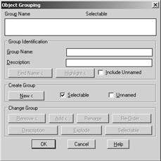
Here are the options available in the Object Grouping dialog box:
Group Identification
Use the Group Identification group to identify your groups, using unique elements that let you remember what each group is for.
Group Name This text box lets you create a new group by naming it first.
Description This text box lets you include a brief description of the group.
Find Name Click this button to find the name of a group. The Object Grouping dialog box temporarily closes so you can click a group.
Highlight Click this button to highlight a group that has been selected from the group list. This helps you locate a group in a crowded drawing.
Include Unnamed This check box determines whether unnamed groups are included in the Group Name list. Check this box to display the names of copies of groups for processing by this dialog box.
Create Group
Here's where you control how a group is created.
New Click this button to create a new group. The Object Grouping dialog box closes temporarily so that you can select objects for grouping. To use this button, you must have either entered a group name or selected the Unnamed check box.
Selectable This check box lets you control whether the group you create is selectable. See the description of the Selectable button in the Change Group button group in the section that follows.
Unnamed This check box lets you create a new group without naming it.
Change Group
These buttons are available only when a group name is highlighted in the Group Name list at the top of the dialog box.
Remove Lets you remove objects from a group.
Add Lets you add objects to a group. While using this option, grouping is temporarily turned off to allow you to select objects from other groups.
Rename Lets you rename a group.
Re-Order Lets you change the order of objects in a group.
Description Lets you modify the description of a group.
Explode Separates a group into its individual components.
Selectable Turns individual groupings on and off. When a group is selectable, it is selectable only as a group. When a group is not selectable, the individual objects in a group can be selected, but not the group.
| Tip | If a group is selected, you can remove individual items from the group with a Shift+click. In this way, you can isolate objects within a group for editing or removal without having to temporarily turn off groups. |
Working with the LT Group Manager
LT only If you are using AutoCAD LT, you use the Group Manager to manage groups. Here is a rundown of the tools that are available in the Group Manager.
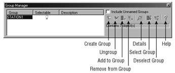
Create Group Lets you convert a set of objects into a group. Select a set of objects and then click Create Group.
Ungroup Removes the grouping of an existing group. Select the group name from the list and then select Ungroup.
Add To Group Lets you add an object to a group. At least one group and one additional object must be selected before this option is available.
Remove From Group Lets you remove one or more objects from a group. To isolate individual objects in a group, first select the group, and then Shift+click to remove individual objects from the selection set. After you isolate the object you want to remove, click Remove From Group.
Details Lists detailed information about the group, such as the number of objects in the group and whether it is in Model Space or a layout. Select the group name from the group list and then click Details.
Select Group Lets you select a group by name. Highlight the group name in the group list and then click Select Group.
Deselect Group Removes a group from the current selection set. Highlight the group name in the group list and then click Deselect Group.
Help Opens the AutoCAD LT Help dialog box and shows you information about the Group Manager.
| Tip | You've seen how you can use groups to create an office layout. You can also use groups to help you keep sets of objects temporarily together in a complex drawing. Groups can be especially useful in 3D modeling when you want to organize complex assemblies together for easy selection. |
EAN: 2147483647
Pages: 261