Finding the Area of Closed Boundaries
One of the most frequently sought pieces of data you can extract from an AutoCAD drawing is the area of a closed boundary. In architecture, you want to find the area of a room or the footprint of a building. In civil engineering, you want to determine the area covered by the boundary of a property line or the area of cut for a roadway. In this section, you'll learn how to use AutoCAD to obtain exact area information from your drawings.
| Tip | To find absolute coordinates in a drawing, use the ID command. Choose Tools Inquiry ID Point or type ID |
Finding the Area of an Object
Architects, engineers , and facilities planners often need to know the square footage of a room or a section of a building. A structural engineer might want to find the cross-sectional area of a beam. In this section, you will practice determining the areas of regular objects.
First, you will determine the square- foot area of the living room and entry of your studio unit plan:
-
On the CD Start AutoCAD. Open the Unit file you created earlier or use the 14a-unit.dwg file from the companion CD.
-
Enter Blipmode
 on . This turns on a marking feature that displays a tiny cross called a blip whenever you click in the drawing area. Blips do not print and can be cleared from the screen with a redraw , as you might recall from Chapter 6. You'll use them to help keep track of your point selections in this exercise.
 -
Zoom in to the living room and entry area so you have a view similar to Figure 14.1.
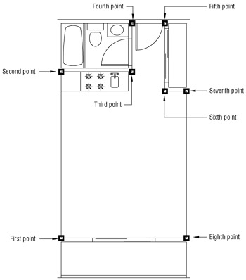
Figure 14.1: Selecting the points to determine the area of the living room and entry -
Choose Tools Inquiry Area or type Area
at the command prompt. Tip You can also select the Area command from the Inquiry toolbar. Right-click any toolbar and choose Inquiry from the shortcut menu.
-
Using the Endpoint Osnap, start with the lower-left corner of the living room and select the points shown in Figure 14.1. You are indicating the boundary.
-
When you have come full circle to the eighth point shown in Figure 14.1, press
. You get the following message: Area = 39570.00 square in. (274.7917 square ft), Perimeter = 76'-0"
-
Now turn off Blipmode by typing Blipmode
off . Then choose View Redraw to clear the blips from the screen.
There is no limit to the number of points you can pick to define an area, so you can obtain the areas of very complex shapes . Use the Blipmode feature to keep track of the points you select so you know when you come to the beginning of the point selections.
Using Boundary
By using the Object option of the Area command, you can also select circles and polylines for area calculations. By using this option in conjunction with another AutoCAD utility called Boundary, you can quickly get the area of a bounded space. Recall from the discussion on hatch patterns in Chapter 6 that when you use the Hatch function, you draw a region polyline; Boundary works similarly. Whereas Hatch generates a hatch pattern that conforms to the outline of a boundary, Boundary generates a polyline outline without adding the hatch.
The following steps show you how to use the Boundary utility:
-
Set the current layer to Floor.
-
Turn off the Door and Fixture layers . Also make sure the Ceiling layer is turned on. You want the boundary to follow the interior wall outline, so you need to turn off any objects that will affect the outline, such as the door and kitchen.
-
Choose Draw Boundary or type bo
to open the Boundary Creation dialog box. Notice that it is actually the Boundary Hatch dialog box with several of the options dimmed. 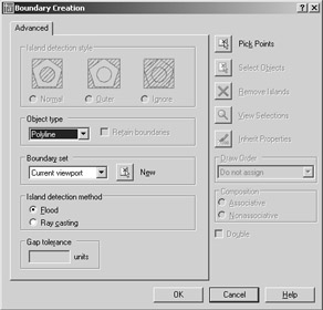
Warning If the area you're trying to measure has gaps, try using the Hatch tool to create a polyline outline. Click the Hatch tool from the Draw toolbar then, in the advanced tab, turn on the Retain Boundaries option and set the Gap Tolerance setting to a value higher than the size of the gaps. Hatch the area, then delete the hatch. A closed polyline of the area will remain .
-
Click the Pick Points button. The Boundary Creation dialog box closes .
-
At the Select internal point: prompt, click in the interior of the unit plan. The outline of the interior is highlighted (see Figure 14.2).
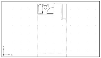
Figure 14.2: After you select a point on the interior of the plan by using Boundary, an outline of the area is highlighted by a dotted line. -
Press
. Boundary draws an outline of the floor area by using a polyline. Because the current layer is Floor, the boundary is drawn on the Floor layer and given the default cyan color of the layer. -
Choose Tools Inquiry Area again or type Area
at the command prompt. Then enter O for the Object option. -
Click the boundary; when it is highlighted, press
. Again you get the following message: Area = 39570.00 square in. (274.7917 square ft), Perimeter = 76'-0"
Tip If you need to recall the last area calculation value you received, enter ¢ Setvar
Area . The area is displayed in the prompt. Enter ¢ Perimeter to get the last perimeter calculated.
The Boundary command creates a polyline that conforms to the boundary of an area. This feature, combined with the ability of the Area command to find the area of a polyline, makes short work of area calculations. As you saw in step 3, Boundary uses the same dialog box as Boundary Hatch. See Chapter 6 for the options available in the Boundary Hatch dialog box.
Finding the Area of Complex Shapes
The Boundary command works fine as long as the area does not contain islands that you do not want included in the area calculation. An island is a closed area within a larger closed area (see Chapter 6 for more on islands and hatching). In the case of the flange part that you'll use in this section, the islands are the two circles at the lower end (see Figure 14.3).
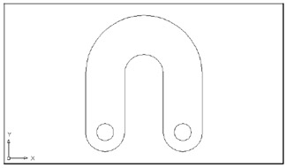
Figure 14.3: A flange to a mechanical device
For areas that contain islands, you must enlist the aid of the other Area command options: Object, Add, and Subtract. By using Add and Subtract, you can maintain a running total of several separate areas being calculated. This gives you flexibility in finding areas of complex shapes. This section guides you through the use of these options.
For the following exercise, you will use a flange shape that contains circles. This shape is composed of simple arcs, lines, and circles. Use these steps to see how you can keep a running tally of areas:
-
On the CD Exit the Unit file and open the file named Flange.dwg from the companion CD (see Figure 14.3). Don't bother to save changes in the Unit file.
-
Choose Draw Boundary to open the Boundary Creation dialog box.
-
Click Pick Points.
-
Click in the interior of the flange shape. Notice that the entire shape is highlighted, including the circle islands.
-
Press
. You now have a polyline outline of the shape. As you saw in the previous exercise, the polyline aids you in quickly obtaining the area. -
Now let's continue by using the Area command's Add and Subtract options. Choose Tools Inquiry Area.
-
Type A
to enter the Add mode, and then type O to select an object. -
Click the outline of the flange. You see the following message:
Area = 27.7080, Perimeter = 30.8496 Total area = 27.7080
-
Press
to exit the Add mode. -
Type S
to enter the Subtract mode, and then type O to select an object. -
Click one of the circles. You see the following message:
Area = 0.6070, Perimeter = 2.7618 Total area = 27.1010
This shows you the area and perimeter of the selected object, and a running count of the total area of the flange outline minus the circle.
-
Click the other circle. You see the following message:
Area = 0.6070, Perimeter = 2.7618 Total area = 26.4940
Again, you see a listing of the area and perimeter of the selected object along with a running count of the total area, which now shows a value of 26.4940. This last value is the true area of the flange.
-
Press
twice to exit the Area command.
In this exercise, you first selected the main object outline and then subtracted the island objects. You don't have to follow this order; you can start by subtracting areas to get negative area values and then add other areas to come up with a total. You can also alternate between Add and Subtract modes, in case you forget to add or subtract areas.
You might have noticed that the Area command prompt offered Specify first corner point or [Object/Add/Subtract]: as the default option for both the Add and Subtract modes. Instead of using the Object option to pick the circles, you can start selecting points to indicate a rectangular area, as you did in the first exercise of this chapter.
Whenever you press ![]() while selecting points for an area calculation, AutoCAD automatically connects the first and last points and returns the calculated area. If you are in the Add or Subtract mode, you can then continue to select points, but the additional areas are calculated from the next point you pick.
while selecting points for an area calculation, AutoCAD automatically connects the first and last points and returns the calculated area. If you are in the Add or Subtract mode, you can then continue to select points, but the additional areas are calculated from the next point you pick.
As you can see from these exercises, it is simpler to first outline an area with a polyline, wherever possible, and then use the Object option to add and subtract area values of polylines.
In this example, you obtained the area of a mechanical object. However, the same process works for any type of area you want to calculate. It can be the area of a piece of property on a topographical map or the area of a floor plan. For example, you can use the Object option to find an irregular area such as the one shown in Figure 14.4, as long as it is a polyline.
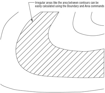
Figure 14.4: The site plan with an area to be calculated
| |
After you find the area of an object, you'll often need to record it somewhere. You can write it down in a project logbook, but this is easy to overlook. A more dependable way to store area information is to use attributes .
Consider the following example: In a building project, you can create a block that contains attributes for the room number, room area, and the date when the room area was last measured. You might make the area and date attributes invisible, so only the room number appears. You can then insert this block into every room. After you find the area, you can easily add it to your block attribute with the Ddatte command. In fact, you can use such a block with any drawing in which you want to store area data. See Chapter 10 for more on attributes.
| |
EAN: 2147483647
Pages: 261
- The Second Wave ERP Market: An Australian Viewpoint
- Enterprise Application Integration: New Solutions for a Solved Problem or a Challenging Research Field?
- The Effects of an Enterprise Resource Planning System (ERP) Implementation on Job Characteristics – A Study using the Hackman and Oldham Job Characteristics Model
- Data Mining for Business Process Reengineering
- Healthcare Information: From Administrative to Practice Databases