6.2 MAP Decoding Algorithm for Convolutional Codes
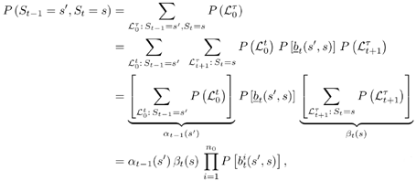
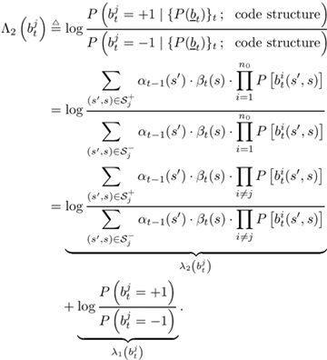
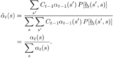
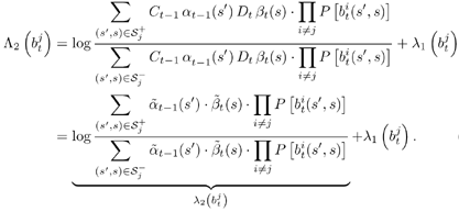
| The input “output relationship of the MAP channel decoder is illustrated in Fig. 6.3. The MAP decoder takes as input the a priori LLRs (or equivalently, probability distributions) of the code (i.e., channel) bits. It delivers as outputs updates of the LLRs of the code bits as well as the LLRs of the information bits, based on the code constraints. In this section we outline a recursive algorithm for computing the LLRs of the code bits and the information bits, which is essentially a slight modification of the celebrated BCJR algorithm [25]. Figure 6.3. Input “output relationship of a MAP channel decoder. Consider a binary rate- k / n convolutional encoder of overall constraint length k n The input to the encoder at time t is a block of k information bits, and the corresponding output is a block of n code bits, The state of the trellis at time t can be represented by a [ k ( n “ 1)]-tuple, as The dynamics of a convolutional code is completely specified by its trellis representation, which describes the transitions between the states at time instants t and t + 1. A path segment in the trellis from t = a to t = b > a is determined by the states it traverses at each time a Denote the input information bits that cause the state transition from S t “1 = s' to S t = s by d ( s' , s ) and the corresponding output code bits by b ( s' , s ). Assuming that a systematic code is used, the pair ( s', b ) uniquely determines the state transition ( s', s ). We next consider computing the probability P ( S t -1 = s' , S t = s ) based on the a priori probabilities of the code bits { P ( b t )} and the constraints imposed by the trellis structure of the code. Suppose that the encoder starts in state S = . An information bit stream { d t } Equation 6.5 Then we have Equation 6.6 where a t ( s ) denotes the total probability of all path segments starting from the origin of the trellis that terminate in state s at time t ; and where b t ( s ) denotes the total probability of all path segments terminating at the end of the trellis that originate from state s at time t . In (6.6) we have assumed that the interleaving is ideal and therefore the joint distribution of b t factors into the product of its marginals: Equation 6.7 The quantities a t ( s ) and b t ( s ) in (6.6) can be computed through the following forward and backward recursions [25]: Equation 6.8 Equation 6.9 with boundary conditions a ( ) = 1, a ( s ) = 0 for s Let Equation 6.10 It is seen from (6.10) that the output of the MAP channel decoder is the sum of the prior information l 1 ( A direct implementation of the recursions (6.8) and (6.9) is numerically unstable, since both a t ( s ) and b t ( s ) drop toward zero exponentially. For sufficiently large t , the dynamic range of these quantities will exceed the range of any machine. To obtain a numerically stable algorithm, these quantities must be scaled as the computation proceeds. Let Equation 6.11 Equation 6.12 with Equation 6.13 For each t Equation 6.14 Equation 6.15 with Equation 6.16 Now by a simple induction, we obtain Equation 6.17 Thus we can write Equation 6.18 That is, each a t ( s ) is effectively scaled by the sum over all states of a t ( s ). Let Equation 6.19 Equation 6.20 Because the scale factor c t effectively restores the sum of a t ( s ) over all states to 1, and because the magnitudes of a t ( s ) and b t ( s ) are comparable, using the same scaling factor is an effective way to keep the computation within a reasonable range. Furthermore, by induction, we can write Equation 6.21 Using the fact that Equation 6.22 is a constant that is independent of t , we can then rewrite (6.10) in terms of the scaled variables as Equation 6.23 We can also compute the a posteriori LLR of the information symbol bit. Let Equation 6.24 Note that the LLRs of the information bits are computed only at the last iteration. The information bit Equation 6.25 Finally, since the input to the MAP channel decoder is the LLR of the code bits, { l 1 ( Equation 6.26 The following is a summary of the MAP decoding algorithm for convolutional codes. Algorithm 6.1: [MAP decoding algorithm for convolutional codes]
|
EAN: 2147483647
Pages: 91
- Article 382 Nonmetallic Extensions
- Article 410: Luminaires (Lighting Fixtures), Lampholders, and Lamps
- Article 427: Fixed Electric Heating Equipment for Pipelines and Vessels
- Example No. D5(a) Multifamily Dwelling Served at 208Y/120 Volts, Three Phase
- Example No. D9 Feeder Ampacity Determination for Generator Field Control


 2, we compute


