5.6 Adaptive Space-Time Multiuser Detection in Multipath CDMA
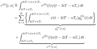
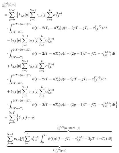
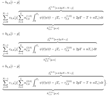
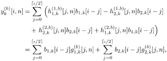
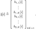
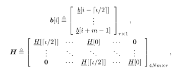
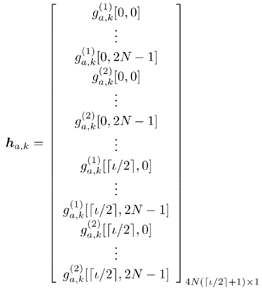
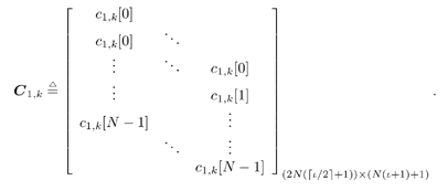
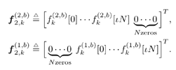
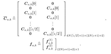
5.6.1 Signal Model In this section we develop adaptive space-time multiuser detectors for asynchronous CDMA systems with two transmit and two receive antennas. The continuous-time signal transmitted from antennas 1 and 2 due to the k th user for time interval i Equation 5.227 Equation 5.228 where M denotes the length of the data frame, T denotes the information symbol interval, and { b k [i] } i is the symbol stream of user k . Although this is an asynchronous system, we have, for notational simplicity, suppressed the delay associated with each user's signal and incorporated it into the path delays in (5.230). We assume that for each k the symbol stream, { b k [i] } i , is a collection of independent random variables that take on values of +1 and -1 with equal probability. Furthermore, we assume that the symbol streams of different users are independent. As discussed in Chapter 2, for the direct-sequence spread-spectrum (DS-SS) format, the user signaling waveforms have the form Equation 5.229 where N is the processing gain, { c q,k [ j ]}, q Equation 5.230 where The received signal component due to the transmission of Equation 5.231 Equation 5.232 Substituting (5.228) and (5.230) into (5.232), we have for receive antenna b Equation 5.233 For a, b, q Equation 5.234 In (5.234), Equation 5.235 The total received signal at receive antenna b Equation 5.236 At the receiver, the received signal is match-filtered to the chip waveform and sampled at the chip rate (i.e., the sampling interval is T c , N is the total number of samples per symbol interval, and 2 N is the total number of samples per time slot). The n th matched-filter output during the i th time slot is given by Equation 5.237 Denote the maximum delay (in symbol intervals) as Equation 5.238 Substituting (5.235) into (5.237), we obtain Equation 5.239 Further substitution of (5.234) into (5.239) shows that Equation 5.240 We may write Equation 5.241 where Equation 5.242 Equation 5.243 For j = 0,1, . . . ,[ I /2], define the following notation: Equation 5.244 Equation 5.245 Equation 5.246 Then we have To exploit both temporal and spatial diversity, we stack the vectors received from both receive antennas, and observe that Equation 5.247 where By stacking m successive received sample vectors, we create the following quantities : where Equation 5.248 We will see in Section 5.6.3 that the smoothing factor, m , is chosen such that Equation 5.249 for channel identifiability. Note that the columns of H (the composite signature vectors) contain information about both the timings and the complex path gains of the multipath channel of each user. Hence an estimate of these waveforms eliminates the need for separate estimates of the timing information 5.6.2 Blind MMSE Space-Time Multiuser DetectionSince the ambient noise is white (i.e., E { v [ i ] v [ i ] H } = s 2 I 4 Nm ), the autocorrelation matrix of the received signal in (5.248) is Equation 5.250 Equation 5.251 where (5.251) is the eigendecomposition of R . The matrix U s has dimensions 4 Nm x r and U n has dimensions 4 Nm x (4 N m “ r ). The linear MMSE space-time multiuser detector and corresponding bit estimate for b a,k [ i ] ,a Equation 5.252 Equation 5.253 The solution to (5.252) can be written in terms of the signal subspace components as Equation 5.254 where 5.6.3 Blind Adaptive Channel EstimationIn this section we extend the blind adaptive channel estimation technique described in Section 5.6.2 to the asynchronous multipath case. First, however, we describe the discrete-time channel model in order to formulate an analog to the optimization problem in (5.208). Discrete-Time Channel ModelUsing (5.244), it is easy to see that Equation 5.255 From (5.241) we have for j = 0, . . . , [ I /2]; n = 0, . . . , 2 N “ 1; b = 1,2, Equation 5.256 Equation 5.257 We will develop the discrete-time channel model for Equation 5.258 From (5.240) we can also see that the sequences Then we have Equation 5.259 where A similar development for Equation 5.260 where The final task in the section is to form expressions for the composite signature waveforms h 1, k and h 2, k in terms of the signature matrices C 1, k , C 2, k and the channel response vectors Equation 5.261 where Blind Adaptive Channel EstimationThe blind channel estimation problem for the asynchronous multipath case involves the estimation of f a,k from the received signal r [ i ]. As we did for the synchronous case, we exploit the orthogonality between the signal subspace and noise subspace. Specifically, since U n is orthogonal to the column space of H , we have Equation 5.262 Denote by z [ i ] the projection of the received signal r [ i ] onto the noise subspace: Equation 5.263 Equation 5.264 Using (5.262), we have Equation 5.265 Our channel estimation problem, then, involves solution of the optimization problem Equation 5.266 subject to the constraint f = 1. If we denote Note that a necessary condition for the channel estimate to be unique is that the matrix Equation 5.267 Using the same constraint, we find that for a fixed m , the maximum number of users that can be supported is Equation 5.268 Equation (5.268) illustrates one of the benefits of the proposed space-time receiver structure over the linear diversity structure. Notice that for reasonable choices of m and I , (5.268) is larger than the maximum number of users for the linear diversity receiver structure, given by Equation 5.269 Another significant benefit of the space-time receiver is reduced complexity. The diversity structure requires four independent subspace trackers operating simultaneously since the receiver performs detection on each of the four received signals, and each has a different signal subspace. Since we stack received signal vectors before detection, the space-time structure requires only one subspace tracker. Once an estimate of the channel state, Algorithm 5.6: [Blind adaptive linear space-time multiuser detector ”asynchronous multipath CDMA, two transmit antennas, and two receive antennas]
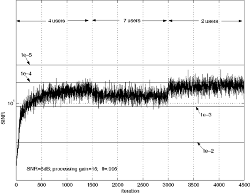
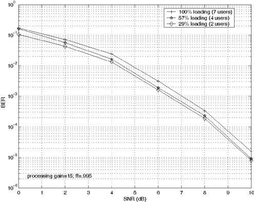
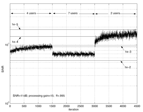
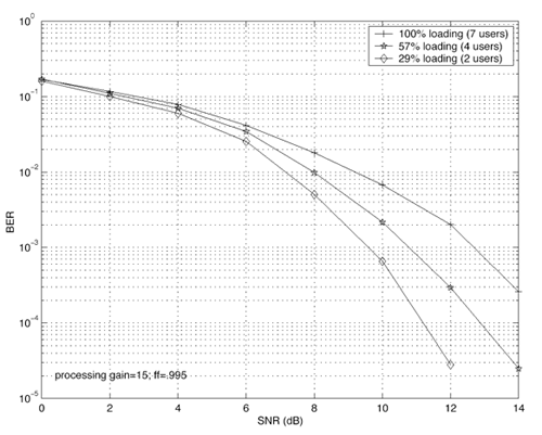
Simulation ResultsIn what follows we present simulation results to illustrate the performance of blind adaptive space-time multiuser detection. We first look at the synchronous flat fading-case; then we consider the asynchronous multipath-fading scenario. For all simulations we use the two transmit/two receive antenna configuration. Gold codes of length 15 are used for each user. The chip pulse is a raised cosine with roll-off factor 0.5. For the multipath case, each user has L = 3 paths. The delay of each path is uniform on [0, T ]. Hence, the maximum delay spread is one symbol interval (i.e., I = 1). The fading gain for each user's channel is generated from a complex Gaussian distribution and is fixed for all simulations. The path gains in each user's channel are normalized so that each user's signal arrives at the receiver with the same power. The smoothing factor is m = 2. For SINR plots, the number of users for the first 1500 iterations is four. At iteration 1501, three users are added so that the system is fully loaded. At iteration 3001, five users are removed. For the steady-state bit-error-probability plots, the frame size is 200 bits and the system is allowed 1000 bits to reach steady state before errors are checked. The forgetting factor for the subspace tracking algorithm for all simulations is 0.995. The performance measures are bit-error probability and the signal-to-interference-plus-noise ratio, defined by Figure 5.14. Adaptation performance of space-time multiuser detection for synchronous CDMA. The labeled horizontal lines represent bit-error-probability thresholds. Figure 5.14 illustrates the adaptation performance for the synchronous case. The SNR is 8 dB. Notice that the BER does not drop below 10 -3 even when users enter or leave the system. Figure 5.15 shows the steady-state performance for the synchronous case for different system loads. We see that the performance changes little as the system load changes. Figure 5.15. Steady-state performance of space-time multiuser detection for synchronous CDMA. Figure 5.16 shows the adaptation performance for the asynchronous multipath case. The SNR for this simulation is 11 dB. Again, notice that the BER does not drop significantly as users enter and leave the system. Figure 5.16. Adaptation performance of space-time multiuser detection for asynchronous multipath CDMA. The labeled horizontal lines represent BER thresholds. Figure 5.17 shows the steady-state performance for the asynchronous multipath case for different system loads. It is seen that system loading has a more significant effect on performance for the asynchronous multipath case than it does for the synchronous case. Figure 5.17. Steady-state performance of space-time multiuser detection for asynchronous multipath CDMA. |
EAN: 2147483647
Pages: 91












 )
)  2
2 