Example 1: NOP Information Packet
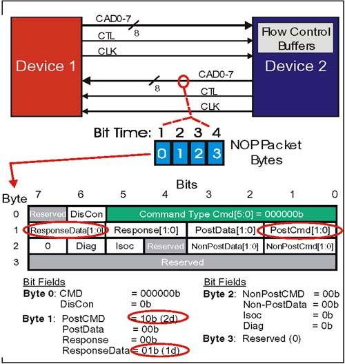
Example 1: NOPInformation PacketProblem: Device 2 in Figure 7-1 on page 145 is using a NOP packet to inform Device 1 about the availability of two new Posted Request (CMD) entries and one new Response (Data) entry in its receiver flow control buffers. Figure 7-1. Example 1: NOP Information Packet With Buffer Updates Example 1: NOP Packet Setup(Refer to Figure 7-1 on page 145.) Command[5:0] Field (Byte 0, Bit 5:0)The NOP information packet command code. There are no option bits within this field. For this example, field = 000000b. DisCon Bit Field (Byte 0, Bit 6)This bit is set to indicate an LDTSTOP# sequence is beginning. Not active for this example. Refer to "HT Link Disconnect/Reconnect Sequence" on page 223 for a discussion of the DisCon bit and the LDTSTOP# sequence. For this example, field = 0b. PostCMD[1:0] Field (Byte 1, Bits 1:0)This NOP field is used by all devices to dynamically report the number of new entries (0-3) in the receiver's Posted Request (CMD) flow control buffers which have become available since the last NOP reporting this information was sent. In our example, assume that two new entries have become available. For this example, field = 10b. PostData[1:0] Field (Byte 1, Bits 3:2)This NOP field is used by all devices to dynamically report the number of new entries (0-3) in the receiver's Posted Request (Data) flow control buffers which have become available since the last NOP reporting this information was sent. In our example, assume no new entries in this buffer have become available. For this example, field = 00b. Response[1:0] Field (Byte 1, Bits 5:4)This NOP field dynamically reports the number of new entries (0-3) in the receiver's Response (Data) flow control buffers which have become available since the last NOP reporting this information was sent. In our example, assume no new entries in this buffer have become available. For this example, field = 00b. ResponseData[1:0] Field (Byte 1, Bits 3:2)This NOP field is used by all devices to dynamically report the number of new entries (0-3) in the receiver's Response (Data) flow control buffers which have become available since the last NOP reporting this information was sent. In our example, assume one new entry in this buffer has become available. For this example, field = 01b. Non-PostCMD[1:0] Field (Byte 2, Bits 1:0)This NOP field dynamically reports the number of new entries (0-3) in the receiver's Non-Posted Request (CMD) flow control buffers which have become available since the last NOP reporting this information was sent. In our example, assume that no new entries have become available. For this example, field = 00b. Non-PostData[1:0] Field (Byte 2, Bits 3:2)This NOP field dynamically reports the number of new entries (0-3) in the receiver's Non-Posted Request (Data) flow control buffers which have become available since the last NOP reporting this information was sent. In our example, assume no new entries in this buffer have become available. For this example, field = 00b. Isoc Bit Field (Byte 2, Bit 5)If set, this NOP field indicates that all six flow control buffer updates contained within this NOP should be applied to the transmitter's isochronous flow control buffer counter set. In our example, assume that the update applies to the standard flow control buffer entries. For this example, field = 0b. Diag Bit Field (Byte 2, Bit 6)If set, this NOP field indicates the transmitter is entering the CRC diagnostic test mode. In this example, this bit is cleared. For this example, field = 0b. Bits Not MentionedReserved bits in bytes 0,1; these should be driven = 0. Example 1: NOP Sequence Of Events On The Link(Refer to Figure 7-1 on page 145) NOP packets are sent continuously during idle times on each link. Because they aren't subject to flow control and don't have data or response packets associated with them, the sequence of events is simple. For the example in Figure 7-1 on page 145:
|
EAN: 2147483647
Pages: 182