8.5 IS-IS
| IS-IS, or Intermediate System to Intermediate System, is a hierarchical link IGP similar in function to OSPF. IS-IS is rooted in the DECnet Phase V routing protocol designed by Radia Perlman around 1985 and standardized by the International Standards Organization (ISO) in 1988. The ISO had implemented IS-IS for use with Connectionless Network Protocol (CLNP), but IS-IS could be extended for use with any Layer 3 protocol. CLNP specified IS-IS and End System to Intermediate System (ES-IS) communications parameters. End systems are devices that send and receive data, such as PCs. Intermediate systems are those that primarily forward data (but can send and receive data as required), such as routers. IS-IS defines the communications parameters between intermediate system devices. IS-IS was then extended to cover IP routing in addition to CLNP. This extended protocol is sometimes known as Integrated IS-IS or Dual IS-IS. RFC 1195 (December 1990) is the proposed IETF standard. Since 1990, many implementations of IS-IS have added features that have gone above and beyond the proposed standard. Three common practice, or informational, RFCs were drafted in 2000. These newer IS-IS RFCs are 2763, 2966, and 2973. Another version of IS-IS was developed for the Internetwork Packet Exchange (IPX) protocoland was named NetWare Link State Routing Protocol (NLSP) (although NLSP and IS-IS are not compatible). So, as you can see, the IS-IS design is flexible enough to be used with many Layer 3 protocols, but IP is the protocol we are concerned with in this book. 8.5.1 IS-IS OverviewHow does a routing protocol that was designed originally for CLNP differ from OSPF, which is designed specifically for IP? There are the following differences:
For the most part, however, IS-IS and OSPF have the following root features in common:
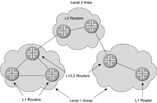
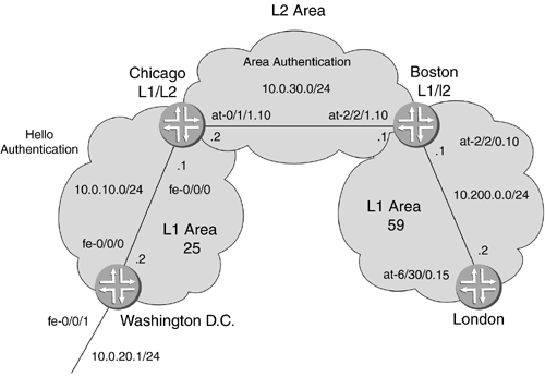
If you recall, OSPF had a backbone area called area 0, with all other areas attached to it. IS-IS also has multiple areas, called Level 1 areas and Level 2 areas, with Level 2 areas representing the backbone and having the same function as area 0 in OSPF. Figure 8-30 shows several Level 1 areas connected through Level 1/2 (L1/2) routers to a Level 2 area. Figure 8-30. IS-IS Areas The L1/L2 routers have the same function as ABRs in OSPF. They filter unnecessary advertisements into a Level 1 area and can summarize network advertisements out of a Level 1 area. In IS-IS and OSPF each router has an RID used for election purposes (DR configured priority, notwithstanding) and for identification in the link state topology database. Because of the origin of IS-IS, a CLNP-type address is used instead of an IP address to identify the router to other routers. Unlike OSPF, which will use an IP address, this CNLP address must be configured manually on the loopback, and all interfaces that will participate in IS-IS must be configured to use the loopback address. Going back to the interface configuration in Chapter 7, the family iso command is used when IS-IS is the IP routing protocol of choice. The ISO address is placed on the loopback interface. All other interfaces that need to run IS-IS have family iso added to their configuration. IS-IS also uses a cost metric and can be configured in the same way as OSPF, but the default metric behavior is slightly different. IS-IS gives all links a default metric of 10 and uses no reference bandwidth until it is configured to do so. It would be wise to set a reference bandwidth, just as in OSPF. 8.5.2 ISO CLNP and AddressingThe CLNP address used for the RID is called a network entity title, or NET. This address is stored as a loopback and is assigned to all of the interfaces that run IS-IS. The interfaces that run IS-IS are called network service access points (NSAPs), which is just another term for an IS-IS-enabled interface. ISO addressing is a bit different than IP addressing. The addresses can range in size from 8 to 20 bytes. There are different levels of ISO addressing. The shortest and least complicated is called a simple NET. This addressing scheme uses one byte for the area, a minimum of six bytes for the system ID, and one last trailing byte for a selector. Figure 8-31 illustrates a simple NET ISO address. The address, written in hexadecimal ( 30.0101.c5af.6001.00 ), is shown in sections. Figure 8-31. IS-IS Simple Net ISO Address In OSPF, the area ID cannot be derived by the RID. In IS-IS the area and RID are combined. In Figure 8-31, the area ID is one byte and the system ID is six bytes. The last byte is the selector byte, which is set to 0. The router's NET on the loopback will normally be configured as 0x00 . IS-IS just takes two similar portions of the identification used in OSPF and combines them. Note For L1 routers to form adjacencies, they must have a common area field. The LSP identifies them as being intra-area. L2 routers can have different area identifiers. There are two other NET types that are more complicated and have more than three parts . These addresses can be as many as 20 bytes in length. These are the ISO NSAP and Government Open Systems Interconnection Profile (GOSIP). The ISO NSAP is 14 bytes in length and has an additional field ”the domain field ”as compared to the simple NET. Figure 8-32 illustrates an ISO NSAP. It the same as the simple NET with an extra six bytes on the front. Figure 8-32. IS-IS ISO NSAP Address The domain field was intended to break large IS-IS networks up into smaller domains, using CLNP extensively. The domain field was to be used for interdomain routing in a manner similar to an AS number for BGP. Since IP has become much more popular than CLNP, this usage has not caught on. GOSIP is the most complicated addressing CLNP scheme. GOSIP addresses are controlled by government authorities, and the fields that make them up are analogous to country codes and area codes in phone numbers . Figure 8-33 shows the fields of a GOSIP address. This address is 20 bytes in length. Figure 8-33. IS-IS GOSIP Address The abbreviations for the field names in Figure 8-33 are defined as follows
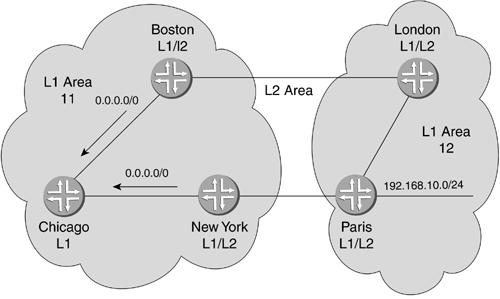
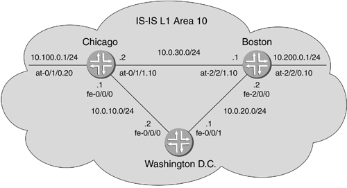
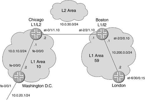
Notice that the end part of the addressing scheme is the same as in the earlier addressing schemes. In some texts , the IDI is also called an ICD, or international code designator. A detailed explanation of the usage of these fields is beyond the scope of this book. Instead, see RFC 1237 "Guidelines for OSI NSAP Allocation in the Internet," at www.ietf.org/rfc.html. 8.5.3 DRsIS-IS elections are very similar to OSPF elections . When an interface is configured for IS-IS, it immediately starts sending out hellos. The priority is checked, and the router with the highest priority becomes the DR. One difference from OSPF is that in IS-IS the DR will change when a higher-priority router is configured onto the link. This behavior is called preemptive, because a higher priority router can preempt the status quo. This is important to know if a router with a high priority is to be added to a multiaccess link with many routers. Routing processes could be interrupted as all of the adjacencies drop from the old DR and are set up with the new DR. 8.5.4 IS-IS PDUsIS-IS uses three main PDUs to exchange information. These PDU types are hello, link state, and sequence number packets (SNPs). The hello PDU serves the same function as it does in OSPF. The packet is sent out of IS-IS-enabled interfaces to find neighbors. Once neighbors are found, adjacencies can be formed . After an adjacency is established, the hellos continue to inform the adjacent routers that the sending router is still up. There are three types of hello PDUs that IS-IS routers use: L1 broadcast network, L2 broadcast network, and any point-to-point network. Link state PDUs (LSPs) are quite similar to LSAs in OSPF. They allow the exchange of route information between IS-IS-enabled routers. The main difference is that in OSPF there are many types of LSAs, each carrying different information. In IS-IS, there are two types of LSPs: Level 1 LSPs and Level 2 LSPs. Each contains all of the information for its level. SNPs are used to ensure that all the routers on a link have the same information. They are used in a similar manner as acknowledgments. There are four types of SNPs: Level 1 and Level 2 can each send a partial SNP (PSNP) or a complete SNP (CSNP). A PSNP is similar to an acknowledgment and lists the sequence numbers of the most recent LSPs; however, a PSNP can acknowledge more than one LSP at a time. PSNPs can also request missing LSPs on a multiaccess link. A CSNP contains the latest sequence numbers of all of the LSPs in the database and is used to synchronize the client router's database to the DR's database. 8.5.5 Default Stub AreasBy default, IS-IS L1 areas are in a state similar to an NSSA in OSPF. This means that there are no routes, other than the Level 1 routes for the IS-IS network. The L1 router has no awareness of the intra-area destinations in the routing table. When the route is unknown, the packet is forwarded toward the nearest L1/L2. When an L1/L2 router receives information on other Level 1 routers, it sets an attached field in the L1 LSP, indicating that it is attached to the Level 2 backbone and can forward to destinations that are unknown to the Level 1 routers. When a Level 1 router receives the LSP with the attached field set, it sets a default route to that router. There are no virtual link features in IS-IS. If a Level 2 area is partitioned, a Level 1 area cannot be used to transit the traffic. If an L1/L2 router loses connection to the Level 2 area, it will notify adjacent routers through its LSPs that it is not attached to Level 2 (by ceasing to set the attached field), and the other Level 1 routers will then send their unknown traffic to the next nearest L1/L2 router. 8.5.6 IS-IS Route LeakingL1 routers set default routes to L1/L2 routes. In most cases, for redundancy, there will be more than one L1/L2 router for the L1 area. External and interarea routes can be advertised into the L1 area from specific L1/L2 routers. This is known as route leaking. If only default routes are used to forward traffic out of an L1 area, suboptimal routing can occur when an L1 area has more than one L1/L2 router. Figure 8-34 shows router Chicago in an L1 area. Routers Boston and New York are the L1/L2 routers for Chicago's area. They will both advertise an attached bits area 11. If router Chicago has a better metric to router Boston than New York for the default route, then all of the out-of-area traffic will pass through Boston, even the traffic destined for network 192.168.10.0/24 . Figure 8-34. IS-IS Route Leaking If New York advertises 192.168.10.0/24 into Chicago's area, then the longest match will allow Chicago to forward to New York despite what the default metrics are. New York is leaking the route into area 11. Route leaking can also be used to make a more deterministic forwarding decision by area routers to spread link usage. If the link between New York and Paris is underutilized , both routers can be configured to leak a few routes for more efficient use of the L1/L2 routers. Route leaking is accomplished by exporting routes into the IS-IS area from the L1/L2 router that you desire to use as the gateway out of the area for those destinations. Exporting routes will be covered in detail in Chapter 11. 8.5.7 IS-IS Single-Area ConfigurationIS-IS configuration requires an ISO address on the loopback interface. This will be the area ID and RID equivalent. To allow the interface to process incoming IS-IS packets, you use the family iso command in the [edit interfaces (interface) ] configuration. The interface command does not actually involve an address; it simply binds that interface to the ISO address on the loopback interface. Lastly, just as in OSPF, interfaces are assigned to IS-IS in the protocol directory. Figure 8-35 shows a single L1 area 10. All of the ISO addresses for the loopback interface will begin with 10. For the system ID, the IP address of an interface can always be used. This can help you quickly identify the router by the RID when the system ID is a recognizable address that has been configured on the router ( especially the loopback). Figure 8-35. IS-IS Single-Area Configuration For the configuration of the system ID portion of the NET, Washington D.C. and Chicago will use the last two bytes of the fe-0/0/0.0 interface IP address. Boston will use the last two bytes of the fe-2/0/0 IP address. Remember that these values in the address field are hexadecimal. Router Chicago: [edit interfaces lo0] lab@Chicago# set unit 0 family iso address 10.0000.0010.0001.00 [edit interfaces lo0] lab@Chicago# show unit 0 { family iso { address 10.0000.0010.0001.00; } } [edit interfaces lo0] lab@Chicago# Router Washington D.C.: [edit interfaces lo0 unit 0] lab@Wash-DC# set family iso address 10.0000.0010.0002.00 Router Boston: [edit interfaces lo0 unit 0] lab@Boston# set family iso address 10.0000.0020.0002.00 The next step is to add the family iso command to the interfaces that will be included in the IS-IS protocol. [edit interfaces] lab@Chicago# set fe-0/0/0 unit 0 family iso [edit interfaces] lab@Chicago# set at-0/1/0 unit 20 family iso [edit interfaces] lab@Chicago# set at-0/1/1 unit 10 family iso [edit interfaces] lab@Chicago# show . . .cut } at-0/1/0 { atm-options { vpi 0 maximum-vcs 250; } unit 20 { vci 100; family inet { address 10.100.0.1/24; } family iso; } }at-0/1/1 { atm-options { vpi 0 maximum-vcs 250; } unit 10 { vci 200; family inet { address 10.0.30.2/24; } family iso; } }cut . . Finally, you need to configure the interfaces in the routing protocol. Just as in OSPF, if all interfaces will be in the same area, then the set interface all command can be used. When an IS-IS level is not specified for an interface, an L1/L2 is set up by default. To keep only Level 1 on the interfaces, you can disable L2 routing. In addition, the loopback 0 ( lo0 ) interface must be added to ensure that the interface that the NET is configured on is in IS-IS. [edit protocols] lab@Chicago# set isis interface all level 2 disable [edit protocols] lab@Chicago# show isis { interface all; } [edit protocols isis] lab@Wash-DC# set interface lo0 level 2 disable [edit protocols isis] lab@Wash-DC# set interface fe-0/0/0 level 2 disable [edit protocols isis] lab@Wash-DC# set interface fe-0/0/1 level 2 disable [edit protocols isis] lab@Wash-DC# set reference-bandwidth 1g [edit protocols isis] lab@Wash-DC# show reference-bandwidth 1g; interface fe-0/0/0.0 { level 2 disable; } interface fe-0/0/1.0 { level 2 disable; } interface lo0.0 { level 2 disable; } [edit protocols isis] lab@Wash-DC# Now all three routers should have NETs, should have family iso assigned to the interfaces, and should have all interfaces, including the loopback, in IS-IS with Level 2 information disabled. To see on which interfaces IS-IS is implemented, and for which area levels, use the show isis interface command. This will show which interface is in which level, as well as DR information. The DR information is the name of the DR router and the selector bit assigned for the connected interface, as is shown below: lab@Wash-DC> show isis interface IS-IS interface database: Interface L CirID Level 1 DR Level 2 DR L1/L2 Metric fe-0/0/0.0 1 0x2 Chicago.02 Disabled 10/10 fe-0/0/1.0 1 0x3 Wash-DC.03 Disabled 10/10 lo0.0 0 0x1 Passive Disabled 0/0 lab@Wash-DC> To see the status of neighbor adjacencies, use the show isis adjacency command. This command is slightly different from OSPF's show ospf neighbor command, but the function is the same. lab@Wash-DC> show isis adjacency IS-IS adjacency database: Interface System L State Hold (secs) SNPA fe-0/0/0.0 Chicago 1 Up 7 0:90:69:a4:d8:0 fe-0/0/1.0 Boston 1 Up 20 0:90:69:52:94:fc lab@Wash-DC> The contents and state of the LSP database for IS-IS can be shown with the show isis database command. As in OSPF, the sequence number of the LSP is shown. Unlike OSPF, instead of the Age of the advertisement, the Lifetime , or amount of time left to the LSP, is shown. lab@Wash-DC> show isis database IS-IS level 1 link-state database: LSP ID Sequence Checksum Lifetime Attributes Chicago.00-00 0x7 0xbbb 515 L1 Chicago.02-00 0x3 0x95c4 487 L1 Wash-DC.00-00 0x7 0xef53 648 L1 Wash-DC.03-00 0x4 0xd85c 648 L1 Boston.00-00 0x4 0x1003 552 L1 0100.0010.0001.00-00 0x4 0 0 L1 0100.0010.0001.02-00 0x1 0 0 L1 0100.0010.0002.00-00 0x6 0 0 L1 0100.0010.0002.03-00 0x1 0 0 L1 0100.0010.0003.00-00 0x7 0 0 L1 10 LSPs IS-IS level 2 link-state database: LSP ID Sequence Checksum Lifetime Attributes Wash-DC.00-00 0x8 0x28e5 648 L1 L2 0100.0010.0002.00-00 0x7 0 0 L1 L2 2 LSPs lab@Wash-DC> As previously mentioned, the actions, commands, and functions of OSPF and IS-IS are very similar, since they are both Link State Protocols (LSPs). 8.5.8 IS-IS Multiple-Area ConfigurationIn the single-area scenario, Level 2 routing is disabled on all interfaces to create a single Level 1 area. To create a Level 2 area and connect Level 1 areas, L1/L2 routers have to be created. In a large Level 2 area, L2-only routers would be configured. In Figure 8-36, an L2 area connects L1 area 25 and area 59. Figure 8-36. IS-IS L1-L2 Connection Configuring routers Washington D.C. and London is the same as for the single-area configuration example. The loopback addresses are configured, all interfaces are installed in IS-IS with Level 2 disabled, and the reference bandwidth is set. [edit interfaces lo0 unit 0 family iso] lab@Wash-DC# set address 10.0000.0010.0002.00 [edit protocols isis] lab@Wash-DC# set interface all level 2 disable [edit protocols isis] lab@Wash-DC# set reference-bandwidth 1g Router Chicago is an L1/L2 router. After configuring the lo0 interface, the interfaces have to be added to different levels. Be sure to add the loopback to IS-IS. [edit protocols isis] lab@Chicago# set interface fe-0/0/0 level 2 disable [edit protocols isis] lab@Chicago# set interface at-0/1/1.10 level 1 disable [edit protocols isis] lab@Chicago# set interface lo0 [edit protocols isis] lab@Chicago# set reference-bandwidth 1g [edit protocols isis] lab@Chicago# show reference-bandwidth 1g; interface fe-0/0/0.0 { level 2 disable; } interface at-0/1/1.10 { level 1 disable; } interface lo0.0; Looking at the adjacencies of router Chicago, you can see one Level 2 and one Level 1 adjacency. lab@Chicago> show isis adjacency IS-IS adjacency database: Interface System L State Hold (secs) SNPA at-0/1/1.10 Boston 2 Up 26 fe-0/0/0.0 Wash-DC 1 Up 22 0:90:69:9e:80:0 Chicago has full knowledge of all routes that are being advertised from both Level 1 areas. lab@Chicago> show route inet.0: 9 destinations, 9 routes (9 active, 0 holddown, 0 hidden) + = Active Route, - = Last Active, * = Both 10.0.10.0/24 *[Direct/0] 1w2d 02:19:24 > via fe-0/0/0.0 10.0.10.1/32 *[Local/0] 1w2d 02:19:24 Local 10.0.20.0/24 *[IS-IS/15] 00:35:01, metric 20, tag 1 > to 10.0.10.2 via fe-0/0/0.0 10.0.30.0/24 *[Direct/0] 1w2d 02:19:24 > via at-0/1/1.10 10.0.30.2/32 *[Local/0] 1w2d 02:19:24 Local 10.100.0.0/24 *[Direct/0] 1w1d 02:38:17 > via at-0/1/0.20 10.100.0.1/32 *[Local/0] 1w2d 02:19:24 Local 10.150.0.0/24 *[Static/5] 3d 01:50:25 > to 10.100.0.2 via at-0/1/0.20 10.200.0.0/24 *[IS-IS/18] 00:26:58, metric 12, tag 2 > to 10.0.30.1 via at-0/1/1.10 iso.0: 1 destinations, 1 routes (1 active, 0 holddown, 0 hidden) + = Active Route, - = Last Active, * = Both 10.0000.0010.0001.00/64 *[Direct/0] 00:35:33 > via lo0.0 No stub area was configured, but remember, IS-IS defaults to an NSSA (stub with no summaries) when a Level 1 area is attached to a Level 2 area. When Chicago is configured as an L1/L2 area, it filters out all other nonarea 10 routes from area 25 and advertises attached status. Router Washington D.C. may not know about any routes any other router has, but it now has a way to exit area 10. Notice that 10.0.30.0/24 and 10.200.0.0/24 are no longer in the routing table. They have been replaced by a 0.0.0.0/0 default route to router Chicago. lab@Wash-DC> show route inet.0: 5 destinations, 5 routes (5 active, 0 holddown, 0 hidden) + = Active Route, - = Last Active, * = Both 0.0.0.0/0 *[IS-IS/15] 00:30:01, metric 10, tag 1 > to 10.0.10.1 via fe-0/0/0.0 10.0.10.0/24 *[Direct/0] 1w2d 02:21:08 > via fe-0/0/0.0 10.0.10.2/32 *[Local/0] 1w2d 02:21:08 Local 10.0.20.0/24 *[Direct/0] 3d 03:14:36 > via fe-0/0/1.0 10.0.20.1/32 *[Local/0] 3d 03:14:36 Local iso.0: 1 destinations, 1 routes (1 active, 0 holddown, 0 hidden) + = Active Route, - = Last Active, * = Both 10.0000.0010.0002.00/64 *[Direct/0] 00:41:00 > via lo0.0 lab@Wash-DC> 8.5.9 IS-IS Authentication ConfigurationThere are two different ways to configure authentication for IS-IS: global and hello packet. Global is configured for the entire IS-IS routing protocol and any router wishing to form an adjacency. Hello authentication is configured between two particular routers at the interface level. Global IS-IS authentication for IS-IS adjacency is very similar to OSPF. The difference in configuration is that in OSPF under the [edit protocols ospf (area) ] directory, the authentication type is defined and then the key is defined under the [edit protocols ospf area (interface) ] directory. In IS-IS, the configuration for the authentication type and the key configuration can take place globally [edit protocols isis] , under the level [edit protocols isis level #] , or under an interface [edit protocols isis interface (interface) ] . Under the directory [edit protocols isis interface (interface) ] , the authentication-type and authentication-key are used for validation of hello packets. In Figure 8-37, Level 2 will have global authentication configured, while hello authentication will be configured between the Level 1 routers of area 25. The global L2 authentication will require any router that wishes an L2 adjacency with Boston to be configured in the same way. Figure 8-37. IS-IS Authentication Setting up the authentication between router Chicago and router Boston is rather straightforward. This is a levelwide authentication, so it will go under the level directory for Level 2. This example starts with router Boston. [edit protocols isis] lab@Boston# set level 2 authentication-type md5 [edit protocols isis] lab@Boston# set level 2 authentication-key test123 [edit protocols isis] lab@Boston# show reference-bandwidth 1g; level 2 { authentication-key "$f5nCOBEyeWRhdbY2aJn/9"; # SECRET-DATA authentication-type md5; } interface at-2/2/0.10 { level 2 disable; } interface at-2/2/1.10 { level 1 disable; } interface lo0.0; [edit protocols isis] lab@Boston# Once the Level 2 authentication is configured, the interface in Level 1 will be configured for hello authentication. This requires leaving the Level 2 directory and moving into the IS-IS interface directory. The hello authentication is configured on the IS-IS interface and will only affect the IS-IS adjacencies on that link. [edit protocols isis] lab@Chicago# set level 2 authentication-type md5 [edit protocols isis] lab@Chicago# set level 2 authentication-key test123 [edit protocols isis] lab@Chicago# edit interface fe-0/0/0 [edit protocols isis interface fe-0/0/0.0] lab@Chicago# set hello-authentication-type md5 [edit protocols isis interface fe-0/0/0.0] lab@Chicago# set hello-authentication-key 123test [edit protocols isis] lab@Chicago# show reference-bandwidth 1g; level 2 { authentication-key "$pgd/uRSvMX-b2LxUjkqf5Rhc"; # SECRET-DATA authentication-type md5; } interface fe-0/0/0.0 { hello-authentication-key "$P536Ctu1EcApIclex7Hqm"; # SECRET-DATA hello-authentication-type md5; level 2 disable; } interface at-0/1/1.10 { level 1 disable; } interface lo0.0; How can you tell that authentication is working? With global IS-IS authentication configuration, if any routers wishing to form an adjacency are not properly configured, the adjacency will not form. This differs from hello authentication, which is done between specific neighbors. Look at the adjacencies for router Chicago. Routers Boston and Chicago have had authentication configured, but router Washington D.C. has not. Notice the rejection of adjacency to Washington D.C. [edit protocols isis] lab@Chicago# run show isis adjacency IS-IS adjacency database: Interface System L State Hold (secs) SNPA at-0/1/1.10 Boston 2 Up 22 fe-0/0/0.0 Wash-DC 1 Rejected 11 0:90:69:9e:80:0 [edit protocols isis] lab@Chicago# Add the configuration to Washington D.C., and the adjacency between Washington D.C. and Chicago is now re-established because the adjacency authentication is now the same on both routers. [edit protocols isis interface fe-0/0/0.0] lab@Wash-DC# set hello-authentication-type md5 [edit protocols isis interface fe-0/0/0.0] lab@Wash-DC# set hello-authentication-key 123test [edit protocols isis interface fe-0/0/0.0] lab@Wash-DC# [edit protocols isis interface fe-0/0/0.0] lab@Wash-DC# run show isis adjacency IS-IS adjacency database: Interface System L State Hold (secs) SNPA fe-0/0/0.0 Chicago 1 Up 6 0:90:69:a4:d8:0 [edit protocols isis interface fe-0/0/0.0] lab@Wash-DC# This section has demonstrated both IS-IS global and hello authentication. Global authentication is for any router on any link to communicate; hello authentication is interface- and link-specific. 8.5.10 Checking IS-IS OperationAs shown in the preceding configuration sections, troubleshooting IS-IS consists of checking the interface, the adjacency states, and the database. The only difference from OSPF in IS-IS show commands is that show isis adjacency is used instead of show ospf neighbor . Checking interfaces will show which interfaces have IS-IS configured, which level they are assigned, the DR for that interface, and what the metric is. lab@Wash-DC> show isis interface IS-IS interface database: Interface L CirID Level 1 DR Level 2 DR L1/L2 Metric fe-0/0/0.0 1 0x2 Chicago.02 Disabled 10/10 fe-0/0/1.0 1 0x3 Wash-DC.03 Disabled 10/10 lo0.0 0 0x1 Passive Disabled 0/0 lab@Wash-DC> Checking the adjacency states will provide information on the relationship with adjoining routers. This includes to which interface the adjacent router is connected, which the adjacent router is, what the state of the relationship is currently, and how long it has been up. lab@Chicago> show isis adjacency IS-IS adjacency database: Interface System L State Hold (secs) SNPA at-0/1/1.10 Boston 2 Up 22 fe-0/0/0.0 Wash-DC 1 Rejected 11 0:90:69:9e:80:0 lab@Chicago> Looking at the contents of the LSDB can assist in ensuring that all the devices that are supposed to be in the area are in fact in the database. Are all of the routers and links listed? Are there supposed to be summaries in the database or just a default route? Checking the routing table is most important. The whole purpose of using and tuning routing protocols is to ensure that the next-hop is what you expect it to be. This will ensure that the routers have the proper information to make an informed decision for packet forwarding. |
EAN: 2147483647
Pages: 176
- The Four Keys to Lean Six Sigma
- Key #4: Base Decisions on Data and Facts
- Making Improvements That Last: An Illustrated Guide to DMAIC and the Lean Six Sigma Toolkit
- The Experience of Making Improvements: What Its Like to Work on Lean Six Sigma Projects
- Six Things Managers Must Do: How to Support Lean Six Sigma
