8.4 OSPF
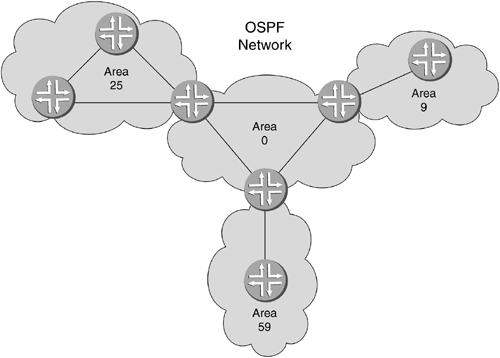
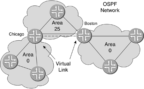
| OSPF is an IGP. The structure for OSPF was first drafted in 1989 by John Moy in RFC 1131, "OSPF Specification." This protocol uses an algorithm called the Dijkstra algorithm, after Edsger Dijkstra, the computer scientist who first described the algorithm to determine which path is best (shortest) between two points. OSPF has gone through many revisions and updates in the IETF drafts since 1989. OSPF version 2 (OSPFv2) is now IETF standard 2328, finalized in 1998, also drafted by John Moy. Note RFCs are mirrored on many other networking or university Web sites. Some of these have search engines that are better than others. The site at www.rfc-editor.org/rfc.html has a good search engine and outputs searches in an easy-to-read format. 8.4.1 Theory of OperationOSPF is a link state routing protocol that permits a router to create a topology database of all the other routers and connections in the network. OSPF is also hierarchical in nature, which means that there is more than one level to its structure. OSPF is implemented in groupings of routers known as areas. The top-level area is known as area 0, or the backbone area, so called because, just as information passing through the human central nervous system must travel through the backbone, any data traveling from one area to another must pass through area 0. Other areas attach to this backbone area. Figure 8-10 illustrates an OSPF network with four areas. Area 0 is connected to areas 9, 25, and 59. Any traffic from area 25, for example, needing to go to area 9 or 59, will need to go through area 0. Figure 8-10. OSPF Hierarchical Areas OSPF uses active communication between neighbor routers on the same link. When neighbors form a communications relationship, called an adjacency , they can send advertisements to each other about the state of the network. The routers have to keep track of the updates they are sending and receiving to ensure that each has the latest information. The updates that OSPF uses are called LSAs. 8.4.2 OSPF MetricsOSPF uses the potential bandwidth of each link along a path for its metric. This is commonly referred to as the cost of the path. These metrics provide more meaningful information than hop count alone because they are not simply hops added along a path. They include the speed of the link. The idea behind an OSPF route is that the lower the cost, the more preferred the network. The default formula used to calculate metrics in OSPF is
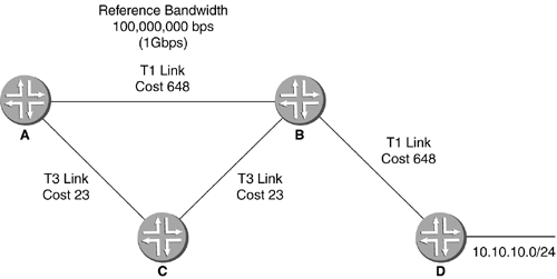
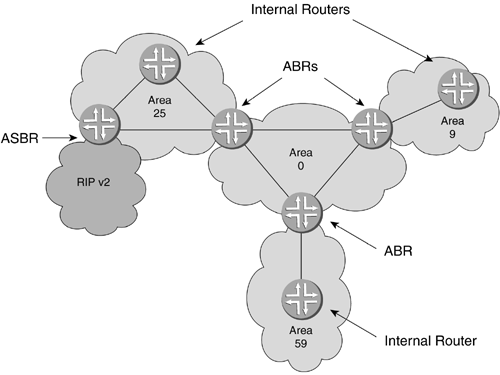
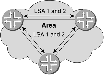
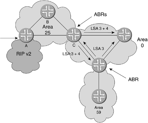
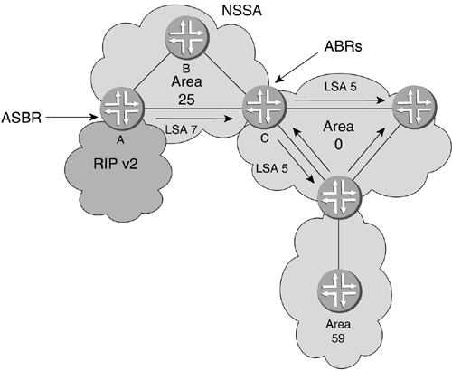
This formula gives a cost of 1 for a 100Mbps connection. When OSPF was being designed, 100Mbps was at the highest end of possible network speeds. Now, this speed is common. Since OSPF metrics have a low end of 1, Fast Ethernet, OC-3 POS, OC-12 ATM, and GigE would all have the same cost, although some links offer bandwidth ten times greater than 100Mbps. To address this discrepancy, Juniper Networks' OSPF implementation allows you to change the 100,000,000 into which the link bandwidth is divided. This is called the reference bandwidth. The reference bandwidth should be set at least as high as the fastest link in the network and must be configured the same on all routers using OSPF. Figure 8-11 shows a network with the corresponding bandwidth of its links. The reference bandwidth is set at 1,000Mbps (1Gbps), and we can see the costs associated with these links. Just as RIP added the hop counts together, OSPF adds costs together when determining the best path to a destination. Figure 8-11. OSPF Links and Metrics In the figure, we see that router A has received router D's update from router B with a total advertised cost of 1,296 for destination network 10.10.10.0/24 . Conversely, the same destination is advertised from router C with a cost of 694, making this the best path in OSPF metrics. If we were using RIP, RIP would just consider the number of hops and would forward to router B. OSPF, however, uses the aggregate bandwidth from all hops to ensure that the overall shortest and most effective path is used. 8.4.3 OSPF AreasThe LSDB keeps track of the routers and links in a single area. As the networks grow, however, this topology table can grow very large. To address this problem, OSPF can be broken into areas, as we mentioned before. The backbone area and each nonbackbone area will have its own smaller LSDB. Links within each nonbackbone area will be advertised to area 0. You can use network summarization to cut down on the number of networks that are advertised from each area into area 0. Two factors to consider when dividing your OSPF network into areas are the size of the LSDB and the capability of the routers in that area. Summarization is the combining of contiguous network advertisements by increasing the scope of the network mask to cover the networks with fewer statements. In other words, instead of advertising four separate but contiguous /24 networks, the routers can advertise one /22 network. In essence, the main purposes of OSPF areas are to reduce the size of the LSDB, to filter advertisements into a nonbackbone area, and to summarize nonbackbone areas into area 0. 8.4.4 Router TypesNotice in Figure 8-12 that some routers have all of their interfaces in the same area, some have interfaces in more than one area, and some have interfaces that use other protocols, such as RIP. These router types are referred to as the internal router (IR), the area border router (ABR), and the autonomous system border router (ASBR). The positions of these routers within the OSPF network are shown in Figure 8-12. Figure 8-12. OSPF Routers The IR router has all its interfaces in the same OSPF area. This router maintains the area topology database of a single area, which stores knowledge about who is where and how to get there cheapest. The ABR is a little different. This router's function is to connect nonbackbone areas to the area 0 backbone. Any traffic going from the connected nonbackbone area to another nonbackbone area will have to pass through this router. This router can also suppress certain external routes (outside OSPF) and advertise default routes in the nonbackbone area. These routers must have a full topology database for every area in which they have an interface. The ASBR router connects more than one autonomous system (AS) together through another routing protocol, such as RIP or BGP. It can also be a router that simply has interfaces in OSPF and also has interfaces in a routing protocol outside OSPF. This router could be the point at which a RIP and OSPF network come together, for example. Since the RIP routes are outside the OSPF process, RIP routes would be seen as external. The ASBR router takes the routes from the other routing protocol and imports them into OSPF. There could be more than one ASBR in an area, some importing routes from another AS, some exporting static routes and some importing RIP routes. This is done with import and export features explained in detail in Chapter 11. 8.4.5 OSPF DatabaseThe OSPF database is the storage area for the topology of a given area in which the router resides. The databases of all the routers in a particular area are the same as each router has a complete map of every router and link in the area. They all have the same picture of the state of the network and the paths to the area destinations. Anytime the database is updated with new information, all the routers will receive the new information and pass it on to adjacent routers. The routers within the area must then converge or return to the steady state where all databases are the same. Once each router in an area receives new information, it must also run the Dijkstra SPF algorithm to update its own LSDB. 8.4.6 AdjacencyOnce OSPF is configured on an interface, it begins sending hello packets. These packets are sent to multicast address 224.0.0.5 . A router sends these hello packets so that all other OSPF-enabled routers in an area are aware of its presence. Even after all OSPF-enabled routers have established communication, hello packets continue to be sent to inform the adjacent routers that the sending router is still alive . A hello packet contains several key pieces of information: router priority, hello interval, router dead interval, a list of all known neighbors, and subnet mask of the attached network. The router priority number is used in a special election process, which will be explained later in Section 8.4.9. The hello interval establishes the frequency with which hello packets will be sent. The router dead interval is the upper limit of time within which a hello packet must be received from an adjacent router or it will be considered down. The subnet mask, in this instance, is for the associated interface. Here is how a router forms an OSPF adjacency. It begins when one OSPF-enabled interface receives a hello packet from another router. Both routers begin exchanging information about their OSPF implementations to ensure that they are compatible. When a router receives a hello containing its own IP address in the known-routers group , it knows that the "handshake" between itself and the neighboring router is valid. The parameters contained in the hello packet for each router will have to match (with the exception of the known-routers list), before the routers will be allowed to exchange OSPF information. Sometimes, an OSPF interface does not need to form adjacencies. If this is the case, you can use the passive interface command to prevent the interface from sending hello packets. Because the interface does not send hellos, it will not form any adjacencies. This can also be used to ensure that a link is seen as internal, as opposed to external, by OSPF. When the routers have agreed on parameters, they begin to exchange OSPF database information. This is known as the exchange state. The routers will keep track of the information in their database and compare it with that of the adjacent router's to ensure that they have the same information. When this exchange is complete, the routers will update all of their neighbors about the new adjacency. The state is now known as full. 8.4.7 LSAsLSAs are the messages that keep the routers informed about the state of the network. Keeping track of an OSPF area means keeping track of the different components of that area, such as router identification (RID) numbers, network summaries, and so on. Because there are many components within an area, there are six different types of LSAs referenced by numbers 1 to 5 and 7. LSA type 6 is a group membership LSA used for a multicast enhancement to OSPF or Multicast Open Shortest Path First (MOSPF) (to learn more about MOSPF, read reference RFC 1584 at www.ietf.org). LSA type 1 represents the router itself. This is how routers tell each other about themselves and the links by which they are connected. LSA type 2 is used to describe broadcast and NBMA networks and the routers attached to those networks. This type of LSA is sent by the Designated Routers (DRs) of those networks (see Section 8.4.9). Figure 8-13 shows that LSA types 1 and 2 stay within the area. Figure 8-13. OSPF LSA Types 1 and 2 LSA type 3 is used for advertising networks or network summaries between different areas within the AS. This LSA type allows for the number of networks listed for other areas to be reduced and is generated by ABRs. LSA type 4 is a summary link to an ASBR generated by the ABR to routers within its area. This LSA type will announce the information about the ASBR for the area. In Figure 8-14, router C is sending a summary of area 25 as an LSA type 3 and an advertisement for router A as an ASBR in a type 4 LSA. Figure 8-14. OSPF LSA Types 3 and 4 LSA type 5 is the LSA for external networks and is generated by the ASBR. LSA type 7 is an optional type of LSA that is used to advertise external routes into a stub area. Stub areas do not allow type 5 routes. Using a type 7 LSA makes the area a not-so-stubby area (NSSA). The ASBR originates type 7 LSAs. Figure 8-15 shows that as these type 7 LSAs reach the ABR for that area, the ABR changes them to type 5s to be sent through the rest of the OSPF areas. Figure 8-15. OSPF LSA Types 5 and 7 This may seem somewhat daunting, but think about what comprises a topology. Routers and networks are the most important things in an OSPF area (using LSA types 1 and 2). Internal and external summaries are next in importance because they tell you how to get to your other areas and ASBRs (using LSA types 3 and 4). Then comes everything outside of your OSPF domain (using types 5 and 7). Here is an example of an OSPF database output on an ABR. This output includes examples of LSA types 1 to 5. lab@Chicago> show ospf database OSPF link state database, area 0.0.0.0 Type ID Adv Rtr Seq Age Opt Cksum Len Router *10.0.10.1 10.0.10.1 0x8000000d 195 0x2 0x7570 48 Router 10.200.0.1 10.200.0.1 0x80000005 385 0x2 0x909f 48 Summary *10.0.10.0 10.0.10.1 0x8000000c 195 0x2 0xc760 28 Summary *10.0.20.0 10.0.10.1 0x80000002 195 0x2 0x77af 28 Summary 10.200.0.0 10.200.0.1 0x80000004 685 0x2 0xdcd5 28 ASBRSum *10.0.20.1 10.0.10.1 0x80000002 195 0x2 0x55d0 28 OSPF link state database, area 0.0.0.25 Type ID Adv Rtr Seq Age Opt Cksum Len Router *10.0.10.1 10.0.10.1 0x80000004 195 0x2 0xdc1d 36 Router 10.0.20.1 10.0.20.1 0x80000009 27 0x2 0xccfa 84 Network 10.0.10.2 10.0.20.1 0x80000001 1317 0x2 0x935d 32 Summary *10.0.30.0 10.0.10.1 0x80000003 195 0x2 0xfc20 28 Summary *10.200.0.0 10.0.10.1 0x80000003 195 0x2 0xe888 28 OSPF external link state database Type ID Adv Rtr Seq Age Opt Cksum Len Extern 10.220.0.0 10.0.20.1 0x80000001 27 0x2 0x19b3 36 lab@Chicago> The following are the names for the LSA types:
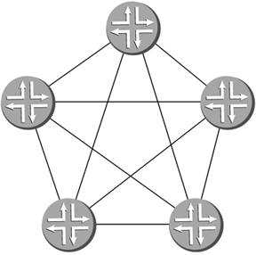
In the example above, you can also see the RID of the advertising router, as well as the sequence number and age of the advertisement. 8.4.8 OSPF Network TypesOSPF is not recommended for a full-mesh network design because of the high processing requirements of such a design. If each router had to form adjacencies with every other network in a 5-router OSPF mesh, there would be 10 adjacencies, whereas a 10-router full mesh would require 45 adjacencies. The formula for a full mesh is N ( N “ 1)/2, where N is the total number of routers. In Figure 8-16, there are five routers that have fully meshed adjacencies. Because each router will be flooding updates, topology changes, and hellos, and because all routers in the area must maintain the same database, you can probably imagine how processor- intensive this could be. You would also waste a great deal of network bandwidth just with routing updates. Figure 8-16. OSPF Full-Mesh Network Configuration Instead of having all routers in an area maintain the same database, one router can maintain the database and update all the other routers at once. Although the other routers maintain their own databases for forwarding decisions, one router will control the flow of advertisements. For multiple access links, a router is chosen from among all the routers to receive updates, keep a master topology database, and update all of the other routers on the shared link. This router is known as the DR. In addition to the DR, a backup DR (BDR) is chosen in case the DR fails. DRs are used on broadcast and NBMA links. These are the links that can have many routers connected at once. Ethernet and ATM are examples of broadcast and NBMA, respectively. OSPF has four basic network types that will determine how adjacencies are formed :
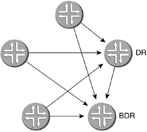
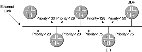
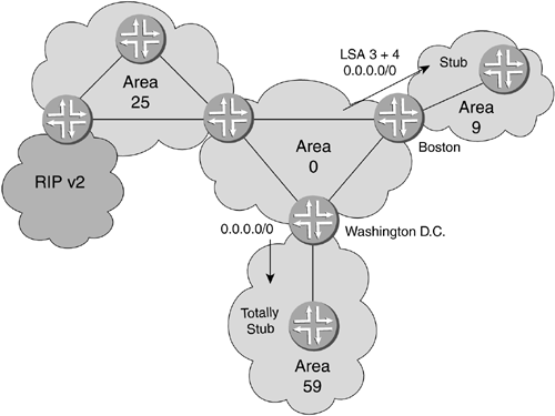
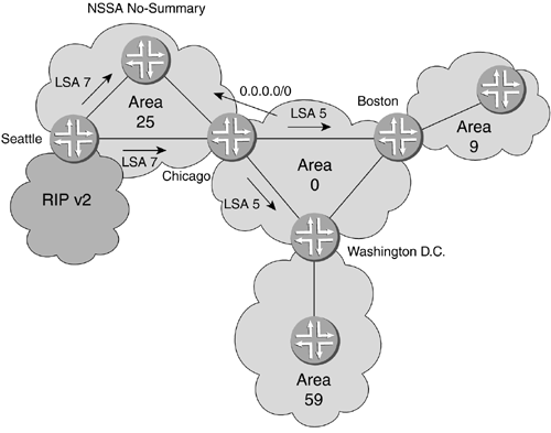
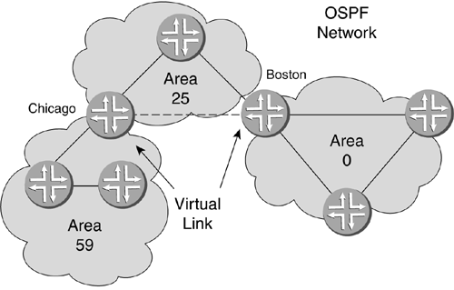
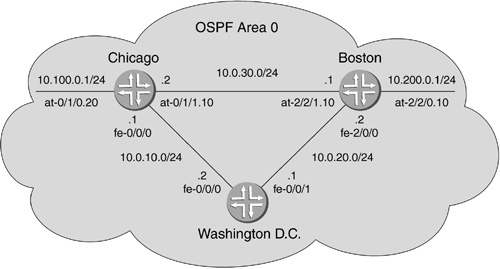
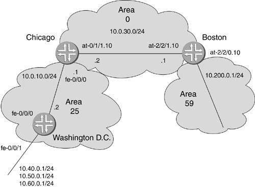
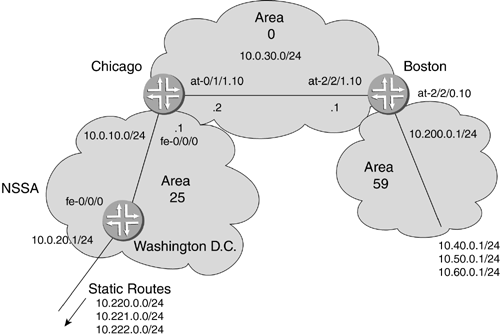
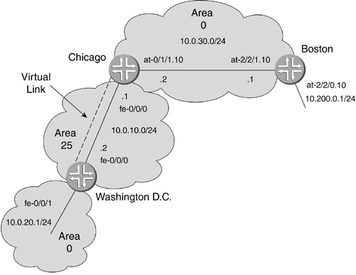
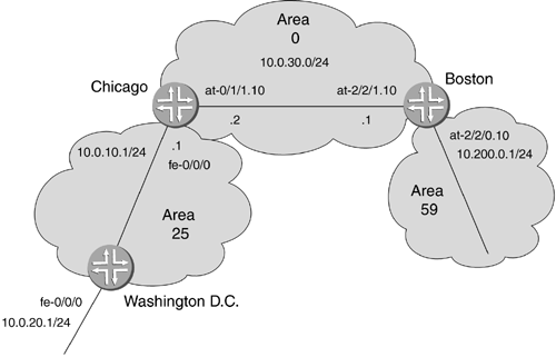
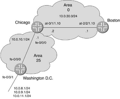
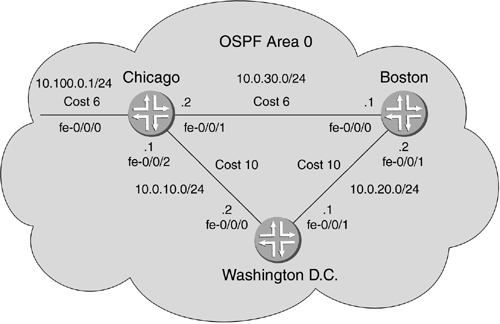
On point-to-point links or point-to-multipoint links, all routers form adjacencies with all other routers on the link in a mesh style. In broadcast or NBMA network types, non-DR/BDR routers adjacencies are formed with all DRs and BDRs. In Figure 8-17, adjacencies are formed only with the DR and BDR. In addition, an adjacency is formed between the DR and BDR. How does a router get to be the DR or BDR? They are elected by all of the routers on that link. Figure 8-17. OSPF DR and BDR Adjacencies 8.4.9 Router ElectionsAs you have just learned, certain OSPF network types use a special router type called the DR, which acts as the leader. All routers on a link hold an election in which they select a DR and a BDR, for redundancy. All other routers form adjacencies with the DR and BDR. This means that instead of 10 routers needing 45 adjacencies to be fully meshed, the eight non-DR routers that are not DR or BDR will form adjacencies with the DR and BDR. When updates need to be sent, the non-DR routers send the updates to the DR and BDR routers, which then send them back out to all the non-DR routers at once. How does this election work? OSPF routers constantly send hello packets out of all OSPF-configured interfaces. The routers all have a priority that is included in the hello packet. The router with the highest priority becomes the DR, and the router with the second highest on the link becomes the BDR. If their priorities are the same, then the router with the highest RID becomes the tiebreaker. An OSPF router's RID is represented as an IP address (usually the highest IP address configured on an interface). On Juniper Networks routers, 128 is the default priority, which is configurable within the range of 0 to 255. If you configure a router to 0 it will never be a DR/BDR. Unless you adminstratively set the priority value, elections will produce a DR and BDR based solely on the RID, which may not be ideal. In Figure 8-18, five routers are on an Ethernet link. Since the routers know this is a broadcast network, a DR and BDR must be elected following the process just described. All of the routers send their priorities along a broadcast (Ethernet) network. The router with a priority of 175 wins DR status, while the router with a priority of 150 becomes the BDR. All of the non-DR/BDR routers form an adjacency with the DR and BDR and start sending LSAs. Figure 8-18. OSPF DR and BDR Elections Bear in mind that there will be circumstances in which it is very desirable to manipulate the DR/BDR election process. The DR and BDR will need a little more processing power. If you have some smaller or older routers on the network, they may not be robust enough to process the updates for several routers in a large area. Another reason to set the priority is that a router may find itself connected to tens, or perhaps hundreds, of broadcast or NBMA networks and wind up as the DR on all of them if one of its interfaces had the highest IP address. This could be disastrous with a small router. If another router comes up on the link with a higher RID or priority, OSPF will not select it as the new DR or BDR unless a new election is held. Because of this attribute, OSPF is considered nonpreemptive. A new election will be held if the current DR becomes disabled. Then the router with higher RID or priority has a chance of becoming the DR. 8.4.10 Stub AreasBreaking an AS into areas allows a router's OSPF databases to remain much smaller. If you want to reduce the database size even further, you can use a special type of OSPF area called a stub area. If there is only one way in and out of a nonzero area, then there is no need for all the backbone routes, other area routes, or external routes. The area routers just need a default route to the ABR. Here we will discuss two methods for automatically filtering routes from outside a nonzero area: stub and totally stubby area and NSSA. 8.4.10.1 Stub and Totally Stubby AreasThe terms stub and totally stubby are used to represent OSPF areas that have partially (stub) and completely (totally stubby) shut off information from outside themselves because it is not necessary for proper operation. In Figure 8-19, area 9 and 59 internal routers have only one way into and out of their areas ”through their ABR. As long as there is a default route in the internal routers' routing tables, area 9 and 59 routers do not need any other information from the network. If there were multiple ABRs to an area, the default routes would have costs added so that the router could select the least-cost path. Figure 8-19. OSPF Stub and Totally Stubby Areas For area 9, router Boston filters out type 5 LSAs from the forwarded advertisements and is therefore a stub area. In addition, router Boston also forwards a default route to area 9 so its routers can route out of the OSPF network. Router Washington D.C. is filtering out all LSAs and only sending a default route. This makes area 59 totally stubby. The difference between these two is whether or not they are sending summary type 3 LSAs. Stub is not as strict as totally stubby. Stub networks allow other area information in, excluding information on external routes. The ABR in a stub will not pass type 5 LSAs, but will pass type 3 LSAs into the area. If an area has more than one ABR, a stub area will allow the area internal routers to make a better decision as to the best path to other areas because interarea routes will be advertised from the ABRs. Totally stubby cuts out type 3, in addition to type 4 and 5, advertisements into an area. The routers only need know about routes to all other internal routers and the default routes to ABRs (sent as a type 3). 8.4.10.2 Not-So-Stubby AreasWhat would happen if, in Figure 8-19, area 25 had been a stub and an external RIP routing process needed to be advertised to the area? External routes generate type 5 LSAs that are not allowed in stub or totally stubby areas. An NSSA allows type 7 LSAs through the area, while still retaining other attributes of a stub area. A type 7 LSA is basically a type 5, but because neither of the stubby area types will allow type 5 LSAs, a type 7 must be used. When type 7 LSAs hit the ABR of the area, they are changed into normal external type 5 LSAs and permitted to continue on throughout the OSPF domain. This allows the ASBRs of the stubby area to keep the routes down to a minimum, but still serve as an entry point for an external routing protocol. In Figure 8-20, router Chicago (ABR) sends no summary LSAs into area 25, but does send in a default route. This NSSA differs from stub and totally stubby areas in that external routes (from the RIP network) have to be propagated. The NSSA configuration allows router Seattle (ASBR) to advertise the RIP networks as type 7 LSAs. Chicago then converts these to type 5 external LSAs for the rest of the OSPF network. This area is an example of an NSSA no-summary area. It receives no summaries other than a default from the ABR and has an ASBR advertising type 7 LSA. Figure 8-20. OSPF NSSA 8.4.11 Equal Cost PathsOSPF can have multiple paths through a network to a destination, such as an ABR or ASBR. Several of the paths can be tied for lowest cost. If such an occurrence takes place, Juniper Networks routers can load balance on the paths of equal cost. Some traffic will take one path; other traffic will travel along the other path. This is called equal cost multipath (ECMP). Juniper Networks implements what is called destination or per-prefix load balancing across up to 16 equal cost paths. This is also known as per-flow load balancing. There is still only one route installed for a particular destination, but if there are four equal cost paths through a single ABR to 400 destinations, Juniper Networks routers will route the flows in round- robin style over the paths so that 100 routes will be assigned to each path. Per-flow load balancing is a feature that was introduced with the Internet Processor II. The original Internet Processor I capable of per-packet load balancing. This meant that packets to the same destination might take different paths. Taking different paths could lead to the packets arriving out of order. Per-flow load balancing sends the packets to the same destination along the same path. 8.4.12 Virtual LinksAn OSPF nonbackbone area must be connected to area 0, the backbone area. OSPF standards dictate that all traffic from one nonbackbone area to another must go through the backbone. In addition, area 0 must not be broken into segments. Since no network is perfectly reliable, there are times when a nonbackbone area could lose its connection to the backbone, or the backbone itself could be separated into several segments due to an area partition. When this occurs, a virtual link must be created to form a temporary repair. In Figure 8-21, notice that area 59 is not directly connected to area 0. Area 59 then needs a virtual link created between router Chicago and router Boston. The dotted line in the figure represents the virtual link from area 59 to area 0 through area 25. This will allow area 59 to participate in the OSPF network as if it were directly attached to area 0 with Chicago as the ABR. Figure 8-21. Creating an OSPF Virtual Link If a failure were to produce a situation in which area 0 was segmented, a virtual link could be created through a nonbackbone area as shown by the dashed line in Figure 8-22. Router Chicago and router Boston are providing the backbone connection to area 59 through area 25 since it isn't directly connected to area 0. Chicago acts as an ABR for area 0 and area 59 as if it were directly connected to area 0. The virtual link is a connection to area 0 that allows the router to act as an ABR connected to area 0. Figure 8-22. Creating a Virtual Link for Area 0 Virtual links are not recommended as a permanent solution. They should be used in temporary situations that arise from failure or unforeseen circumstances. 8.4.13 OSPF Single-Area ConfigurationThe minimum configuration for OSPF on Juniper Networks routers is accomplished by simply adding an interface into an area. In Figure 8-23, we see a single OSPF area. The routers, their addresses, and their interfaces are identified. Once the interfaces are configured, you just need to add them into the OSPF process. Figure 8-23. Configuring an OSPF Single Area Adding an interface into the OSPF process is done from the [edit protocols ospf] level of the configuration hierarchy. The example below shows how to do this. Starting with Chicago, the area is identified followed by the interface. [edit] lab@Chicago# edit protocols ospf [edit protocols ospf] lab@Chicago# set area 0 interface at-0/1/0.20 [edit protocols ospf] lab@Chicago# set area 0 interface at-0/1/1.10 [edit protocols ospf] lab@Chicago# set area 0 interface fe-0/0/0.0 [edit protocols ospf] lab@Chicago# show area 0.0.0.0 { interface at-0/1/0.20; interface at-0/1/1.10; interface fe-0/0/0.0; } [edit protocols ospf] lab@Chicago# Knowing how to add individual interfaces is important when configuring ABRs or ASBRs. They will have interfaces in different areas. For routers that have all interfaces in OSPF and in the same area, however, the command set area x interface all will assign every interface into the specified OSPF area. [edit] lab@Boston# edit protocols ospf [edit protocols ospf] lab@Boston# set area 0 interface all [edit protocols ospf] lab@Boston# show area 0.0.0.0 { interface all; } [edit protocols ospf] lab@Boston# lab@Boston> show ospf interface brief Interface State Area DR ID BDR ID Nbrs at-2/2/0.10 PtToPt 0.0.0.0 0.0.0.0 0.0.0.0 0 at-2/2/1.10 PtToPt 0.0.0.0 0.0.0.0 0.0.0.0 1 fe-2/0/0.0 DR 0.0.0.0 10.0.20.2 10.0.20.1 1 lo0.0 DR 0.0.0.0 10.0.20.2 0.0.0.0 0 lab@Boston> The run show ospf interface brief command shows all OSPF interfaces and their assigned areas. In addition, it will list the DRs, BDRs, and number of neighbors on those links. Once router Washington D.C. has had its interfaces entered in OSPF area 0, all routers will have formed adjacencies and advertised routes. lab@Wash-DC> show route inet.0: 12 destinations, 12 routes (12 active, 0 holddown, 0 hidden) + = Active Route, - = Last Active, * = Both 10.0.10.0/24 *[Direct/0] 00:39:17 > via fe-0/0/0.0 10.0.10.2/32 *[Local/0] 00:39:17 Local 10.0.20.0/24 *[Direct/0] 00:39:17 > via fe-0/0/1.0 10.0.20.1/32 *[Local/0] 00:39:17 Local 10.0.30.0/24 *[OSPF/10] 00:02:09, metric 2 > to 10.0.20.2 via fe-0/0/1.0 to 10.0.10.1 via fe-0/0/0.0 10.100.0.0/24 *[OSPF/10] 00:02:26, metric 2 > to 10.0.10.1 via fe-0/0/0.0 10.200.0.0/24 *[OSPF/10] 00:02:09, metric 2 > to 10.0.20.2 via fe-0/0/1.0 224.0.0.5/32 *[OSPF/10] 00:03:13, metric 1 lab@Wash-DC> This example shows all five networks configured in OSPF. Looking at routes with multiple entries, we see that there are equal cost paths that can be taken to the highlighted destination network. Referring back to Figure 8-23, the cost to network 10.0.30.0/24 from router Washington D.C. should be equal, since both of the links to the network are the same. In this instance, ECMP can be used to load balance to this destination. 8.4.14 OSPF Multiple-Area ConfigurationThe minimum configuration for OSPF in multiple areas is not much different from RIP, with the exception that OSPF does not require an export policy. OSPF will enter the links and networks into the LSDB for the area in which the interfaces are assigned. OSPF will then advertise those LSDB entries to adjacent routers without exporting the routes. In Figure 8-24, area 0 is connecting area 25 and area 59. Interface fe-0/0/1 on the Washington D.C. router has three more network addresses added to populate the routing table with more routes. Figure 8-24. OSPF Multiple Areas With router Washington D.C., use of the quick OSPF command set area x interface all to add all of the interfaces is allowable because all of the interfaces are in the same area. [edit] lab@Wash-DC# edit protocols ospf [edit protocols ospf] lab@Wash-DC# set area 25 interface all [edit protocols ospf] lab@Wash-DC# Router Washington D.C. is now an internal router. For routers Chicago and Boston, each interface must be configured for the appropriate area. [edit] lab@Chicago# edit protocols ospf [edit protocols ospf] lab@Chicago# set area 0 interface at-0/1/1.10 [edit protocols ospf] lab@Chicago# set area 25 interface fe-0/0/0.0 ---- [edit] lab@Boston# edit protocols ospf [edit protocols ospf] lab@Boston# set area 0 interface at-2/2/1.10 [edit protocols ospf] lab@Boston# set area 59 interface at-2/2/0.10 [edit protocols ospf] lab@Boston# Routers Chicago and Boston now need separate OSPF databases for each area in which they have interfaces configured. Taking a look at router Chicago's database in the following example. Notice that the LSAs are grouped by type and by area in ascending order. lab@Chicago> show ospf database OSPF link state database, area 0.0.0.0 Type ID Adv Rtr Seq Age Opt Cksum Len Router *10.0.10.1 10.0.10.1 0x80000002 250 0x2 0x8b65 48 Router 10.200.0.1 10.200.0.1 0x80000002 248 0x2 0x969c 48 Summary *10.0.10.0 10.0.10.1 0x80000002 374 0x2 0xdb56 28 Summary *10.0.20.0 10.0.10.1 0x80000001 374 0x2 0x79ae 28 Summary *10.40.0.0 10.0.10.1 0x80000001 374 0x2 0x749f 28 Summary *10.50.0.0 10.0.10.1 0x80000001 374 0x2 0xfb0e 28 Summary *10.60.0.0 10.0.10.1 0x80000001 374 0x2 0x837c 28 Summary 10.200.0.0 10.200.0.1 0x80000001 249 0x2 0xe2d2 28 OSPF link state database, area 0.0.0.25 Type ID Adv Rtr Seq Age Opt Cksum Len Router *10.0.10.1 10.0.10.1 0x80000003 378 0x2 0xde1c 36 Router 10.0.20.1 10.0.20.1 0x80000004 379 0x2 0xd0fd 84 Network 10.0.10.2 10.0.20.1 0x80000001 379 0x2 0x935d 32 Summary *10.0.30.0 10.0.10.1 0x80000001 419 0x2 0x11e 28 Summary *10.200.0.0 10.0.10.1 0x80000001 245 0x2 0xec86 28 Ultimately, the routes will be in the routing table. Showing the routes on Boston also shows all the routes from Washington D.C. lab@Boston> show route inet.0: 12 destinations, 12 routes (11 active, 0 holddown, 1 hidden) + = Active Route, - = Last Active, * = Both . . . cut 10.0.30.0/24 *[Direct/0] 1d 00:16:21 > via at-2/2/1.10 [OSPF/10] 00:11:00, metric 1 > via at-2/2/1.10 10.0.30.1/32 *[Local/0] 1d 00:16:21 Local 10.40.0.0/24 *[OSPF/10] 00:10:55, metric 3 > via at-2/2/1.10 10.50.0.0/24 *[OSPF/10] 00:10:55, metric 3 > via at-2/2/1.10 10.60.0.0/24 *[OSPF/10] 00:10:55, metric 3 > via at-2/2/1.10 10.200.0.0/24 *[Direct/0] 00:31:19 > via at-2/2/0.10 [OSPF/10] 00:11:00, metric 1 > via at-2/2/0.10 10.200.0.1/32 *[Local/0] 1d 00:16:21 Local . . . . cut Also, notice the metric costs for the routes from router Boston to the far side of router Washington D.C. The metric is three, even though the path is 155Mbps ATM through two 100Mbps Fast Ethernet links. Remember, in Section 8.1.1 we discussed reference bandwidths as they relate to the metric (cost). Changing the reference bandwidth to 1,000Mbps (1Gbps) will show a more accurate cost for the path. The reference bandwidth should be at least equal to your fastest network link in OSPF. After changing the reference bandwidth of all the routers, the metrics will have changed. [edit protocols ospf] lab@Wash-DC# set reference-bandwidth 1000000000 (commit) lab@Boston> show route inet.0: 12 destinations, 12 routes (11 active, 0 holddown, 1 hidden) + = Active Route, - = Last Active, * = Both . . . cut 10.0.30.0/24 *[Direct/0] 1d 00:18:19 > via at-2/2/1.10 [OSPF/10] 00:00:30, metric 6 > via at-2/2/1.10 10.0.30.1/32 *[Local/0] 1d 00:18:19 Local 10.40.0.0/24 *[OSPF/10] 00:00:02, metric 26 > via at-2/2/1.10 10.50.0.0/24 *[OSPF/10] 00:00:02, metric 26 > via at-2/2/1.10 10.60.0.0/24 *[OSPF/10] 00:00:02, metric 26 > via at-2/2/1.10 10.200.0.0/24 *[Direct/0] 00:33:17 > via at-2/2/0.10 [OSPF/10] 00:00:30, metric 6 > via at-2/2/0.10 . . . cut Now the costs more accurately reflect the network state. The Fast Ethernet links will have a higher cost per link than the higher-bandwidth links. 8.4.15 OSPF Stub ConfigurationFiltering the external LSAs with a stub configuration can drastically cut down the size of the routing table for each. Using the same scenario in Figure 8-24 for the multiple-area configuration, the stub configuration can be added to routers Chicago and Washington D.C. Looking at the LSAs on router Washington D.C., notice that there are two summary LSAs. lab@Wash-DC> show ospf database OSPF link state database, area 0.0.0.25 Type ID Adv Rtr Seq Age Opt Cksum Len Router 10.0.10.1 10.0.10.1 0x80000006 848 0x2 0x7b73 36 Router *10.0.20.1 10.0.20.1 0x80000005 1671 0x2 0x3868 84 Network *10.0.10.2 10.0.20.1 0x80000001 2574 0x2 0x935d 32 Summary 10.0.30.0 10.0.10.1 0x80000004 520 0x2 0x2de9 28 Summary 10.200.0.0 10.0.10.1 0x80000004 220 0x2 0x4b1b 28 To change area 25 to a stub network, the configuration must be applied to all the internal routers and ABRs for that particular area. The following example shows the no-summaries option, which will filter out type 3, 4, and 5 LSAs, creating a totally stubby area. If type 3s are to be received and only type 4s and 5s to be filtered, then the no-summaries option is configured. Router Chicago [edit protocols ospf] lab@Chicago# set area 25 stub no-summaries Router Washington D.C. [edit protocols ospf] lab@Wash-DC# set area 25 stub no-summaries lab@Wash-DC> show ospf database OSPF link state database, area 0.0.0.25 Type ID Adv Rtr Seq Age Opt Cksum Len Router 10.0.10.1 10.0.10.1 0x80000003 5 0x0 0x955f 36 Router *10.0.20.1 10.0.20.1 0x80000002 2 0x0 0x5254 84 Network 10.0.10.1 10.0.10.1 0x80000001 5 0x0 0x2ad3 32 lab@Wash-DC> The summary LSAs have been filtered. This is an extremely important feature to use for areas that do not need to know all of the routes. If areas have thousands of routes and there are many areas, the routing engine could be overworked. The stub and totally stubby configuration must be applied to every router in the area to be effective. One final configuration step that must be taken on Washington D.C. because it has been cut off from all route advertisements, is to add a default route to the ABR. With no knowledge of any router outside of area 25, Washington D.C. must have a way to get to routers external to the area. Router Washington D.C. cannot get to router Boston, as shown below when router Washington D.C. tries to ping Boston: lab@Wash-DC> ping 10.0.30.1 PING 10.0.30.1 (10.0.30.1): 56 data bytes ping: sendto: No route to host ping: sendto: No route to host ping: sendto: No route to host ^C --- 10.0.30.1 ping statistics --- 3 packets transmitted, 0 packets received, 100% packet loss To have the ABR advertise a default route into an area, use the default-metric parameter of the area stub command on the ABR. For this scenario, Chicago is the ABR for area 25. Configuration for router Chicago: [edit protocols ospf] lab@Chicago# set area 25 stub default-metric 2 Configuration for router Washington D.C.: lab@Wash-DC> show route inet.0: 12 destinations, 12 routes (12 active, 0 holddown, 0 hidden) + = Active Route, - = Last Active, * = Both 0.0.0.0/0 *[OSPF/10] 00:00:06, metric 3 > to 10.0.10.1 via fe-0/0/0.0 10.0.10.0/24 *[Direct/0] 1d 22:54:50 > via fe-0/0/0.0 10.0.10.2/32 *[Local/0] 1d 22:54:50 Local . . .cut Router Washington D.C. now has a default route that covers anything not known to the area. Washington D.C. can now ping Boston. lab @Wash-DC> ping 10.0.30.1 PING 10.0.30.1 (10.0.30.1): 56 data bytes 64 bytes from 10.0.30.1: icmp_seq=0 ttl=254 time=1.478 ms 64 bytes from 10.0.30.1: icmp_seq=1 ttl=254 time=1.372 ms 64 bytes from 10.0.30.1: icmp_seq=2 ttl=254 time=1.329 ms 64 bytes from 10.0.30.1: icmp_seq=3 ttl=254 time=1.271 ms ^C --- 10.0.30.1 ping statistics --- 4 packets transmitted, 4 packets received, 0% packet loss round-trip min/avg/max/stddev = 1.271/1.363/1.478/0.076 ms lab @Wash-DC> 8.4.16 OSPF NSSA ConfigurationNSSA configuration is similar to stub configuration. The difference is the presence of external routes. The need for an NSSA stems from the requirement to inject external routes into OSPF in that area and the desire to restrict external or summary routes into that area from the other OSPF areas. In Figure 8-25, area 25 has static routes forwarding out of interface fe-0/0/1 . There is a policy named ospf_stat that matches these routes, and they are exported into OSPF. This is shown below in router Washington D.C.'s configuration. Figure 8-25. OSPF NSSA Configuration Before an NSSA area is configured, the database has many different types of LSAs in router Washington D.C., as follows : lab@Wash-DC> show ospf database OSPF link state database, area 0.0.0.25 Type ID Adv Rtr Seq Age Opt Cksum Len Router 10.0.10.1 10.0.10.1 0x80000004 260 0x2 0x7f71 36 Router *10.0.20.1 10.0.20.1 0x80000006 43 0x2 0xd8c7 48 Network *10.0.10.2 10.0.20.1 0x80000001 545 0x2 0x935d 32 Summary 10.0.30.0 10.0.10.1 0x80000002 258 0x2 0x31e7 28 Summary 10.40.0.0 10.0.10.1 0x80000001 42 0x2 0xd831 28 Summary 10.50.0.0 10.0.10.1 0x80000001 42 0x2 0x609f 28 Summary 10.60.0.0 10.0.10.1 0x80000001 42 0x2 0xe70e 28 Summary 10.200.0.0 10.0.10.1 0x80000003 258 0x2 0x4d1a 28 OSPF external link state database Type ID Adv Rtr Seq Age Opt Cksum Len Extern *10.220.0.0 10.0.20.1 0x80000003 546 0x2 0x15b5 36 Extern *10.221.0.0 10.0.20.1 0x80000003 546 0x2 0x9c0 36 Extern *10.222.0.0 10.0.20.1 0x80000001 610 0x2 0x1c9 36 Here we apply the NSSA configuration to router Washington D.C. and router Chicago, not forgetting to set a default metric for generating a default route into area 25. [edit protocols ospf] lab@Chicago# set area 25 nssa no-summaries [edit protocols ospf] lab@Chicago# set area 25 nssa default-lsa default-metric 2 -- [edit protocols ospf] lab@Wash-DC# set area 25 nssa no-summaries (commmit) [edit protocols ospf] lab@Wash-DC# run show ospf database OSPF link state database, area 0.0.0.25 Type ID Adv Rtr Seq Age Opt Cksum Len Router 10.0.10.1 10.0.10.1 0x80000003 15 0x0 0xf803 36 Router *10.0.20.1 10.0.20.1 0x80000002 10 0x0 0xeee2 84 Network 10.0.10.1 10.0.10.1 0x80000001 14 0x0 0x2ad3 32 Summary 0.0.0.0 10.0.10.1 0x80000001 110 0x0 0xf651 28 NSSA *10.220.0.0 10.0.20.1 0x80000001 14 0x8 0x2481 36 NSSA *10.221.0.0 10.0.20.1 0x80000001 14 0x8 0x188c 36 NSSA *10.222.0.0 10.0.20.1 0x80000001 14 0x8 0xc97 36 [edit protocols ospf] lab@Wash-DC# Note In the configuration example shown here, the show ospf database command was run from the configuration mode. This can actually be quite preferrable during configuration. The run option in configuration mode can save you the work of going in and out of configuration mode. Router Washington D.C. sees only the necessary LSAs. The NSSA in the first column represents the type 7 LSA. The only summary LSA is the default route at the ABR. Router Chicago (ABR) is turning type 7 NSSA LSAs into type 5 external LSAs, as shown below: lab@Chicago> show ospf database OSPF link state database, area 0.0.0.0 Type ID Adv Rtr Seq Age Opt Cksum Len Router *10.0.10.1 10.0.10.1 0x80000014 285 0x2 0x591a 48 Router 10.40.0.1 10.40.0.1 0x80000002 641 0x2 0x1456 48 Router 10.200.0.1 10.200.0.1 0x80000007 737 0x2 0x8ca1 48 Summary *10.0.10.0 10.0.10.1 0x80000013 236 0x2 0x1404 28 Summary *10.0.20.0 10.0.10.1 0x80000001 236 0x2 0x2ee7 28 Summary 10.40.0.0 10.40.0.1 0x80000002 13 0x2 0x9f51 28 Summary 10.40.0.0 10.200.0.1 0x80000001 737 0x2 0x6aeb 28 Summary 10.50.0.0 10.40.0.1 0x80000001 646 0x2 0x29be 28 Summary 10.50.0.0 10.200.0.1 0x80000001 737 0x2 0xf15a 28 Summary 10.60.0.0 10.40.0.1 0x80000001 646 0x2 0xb02d 28 Summary 10.60.0.0 10.200.0.1 0x80000001 737 0x2 0x79c8 28 Summary 10.200.0.0 10.40.0.1 0x80000001 646 0x2 0x1a37 28 Summary 10.200.0.0 10.200.0.1 0x80000006 737 0x2 0xd8d7 28 ASBRSum *10.0.20.1 10.0.10.1 0x80000001 236 0x2 0xb16c 28 OSPF link state database, area 0.0.0.25 Type ID Adv Rtr Seq Age Opt Cksum Len Router *10.0.10.1 10.0.10.1 0x80000003 240 0x0 0xa54c 36 Router 10.0.20.1 10.0.20.1 0x80000003 242 0x0 0xfca8 48 Network 10.0.10.2 10.0.20.1 0x80000001 242 0x0 0xb141 32 Summary *0.0.0.0 10.0.10.1 0x80000001 285 0x0 0xf651 28 NSSA 10.220.0.0 10.0.20.1 0x80000001 309 0x8 0x2481 36 NSSA 10.221.0.0 10.0.20.1 0x80000001 309 0x8 0x188c 36 NSSA 10.222.0.0 10.0.20.1 0x80000001 309 0x8 0xc97 36 OSPF external link state database Type ID Adv Rtr Seq Age Opt Cksum Len Extern 10.220.0.0 10.0.20.1 0x80000003 923 0x2 0x15b5 36 Extern 10.221.0.0 10.0.20.1 0x80000003 923 0x2 0x9c0 36 Extern 10.222.0.0 10.0.20.1 0x80000002 366 0x2 0xfeca 36 lab@Chicago> This is the final configuration for router Chicago and router Washington D.C. (export policies are explained in detail in Chapter 11). [edit] lab@Chicago# show cut . . } } protocols { ospf { reference-bandwidth 1g; area 0.0.0.25 { nssa { default-lsa default-metric 2; no-summaries; } interface fe-0/0/0.0; } area 0.0.0.0 { interface at-0/1/1.10; } } } [edit] lab@Chicago# [edit] lab@Wash-DC# cut . . . } } routing-options { static { route 10.220.0.0/24 next-hop 10.0.20.2; route 10.221.0.0/24 next-hop 10.0.20.2; route 10.222.0.0/24 next-hop 10.0.20.2; } } protocols { ospf { export ospf_stat ; reference-bandwidth 1g; area 0.0.0.25 { nssa no-summaries; interface all; } } } policy-options { policy-statement ospf_stat { from protocol static; then accept; } } [edit] lab@Wash-DC# 8.4.17 OSPF Virtual-Link ConfigurationIn order for a virtual link to be created through an area, the virtual link has to be between two routers whose interfaces are in the given area. One router has to be an ABR with interfaces in area 0. The second router has to have an interface in the area that is not attached. In Figure 8-26, area 0 has been partitioned, possibly through a link failure. Area 0 must therefore use area 25 to make the connection between backbone areas through a virtual link until it can be fixed. Figure 8-26. OSPF Virtual Link You first need to configure the virtual link to ensure that the proper far-end RID is referenced in the command as shown below. The destination interface for the virtual link is not necessarily the RID, which is either the highest IP address on the router or the loopback address, if properly configured. [edit protocols ospf] lab@Wash-DC# set area 0 virtual-link neighbor-id 10.0.10.1 transit-area 25 [edit protocols ospf] lab@Wash-DC# show reference-bandwidth 1g; area 0.0.0.25 { interface fe-0/0/0.0; } area 0.0.0.0 { virtual-link neighbor-id 10.0.10.1 transit-area 0.0.0.25; interface fe-0/0/1.0; } [edit protocols ospf] lab@Wash-DC# [edit protocols ospf] lab@Chicago# set area 0 virtual-link neighbor-id 10.0.20.1 transit-area 25 [edit protocols ospf] lab@Chicago# show reference-bandwidth 1g; area 0.0.0.25 { interface fe-0/0/0.0; } area 0.0.0.0 { virtual-link neighbor-id 10.0.20.1 transit-area 0.0.0.25; interface at-0/1/1.10; } The best way to ensure that the virtual link is up is to use the show ospf interface command as shown below. This will show the status of the virtual link and neighbor on the far end. If the neighbor ID is set incorrectly, then the status will be down for that link. lab@Chicago> show ospf interface Interface State Area DR ID BDR ID Nbrs at-0/1/1.10 PtToPt 0.0.0.0 0.0.0.0 0.0.0.0 1 vl-10.0.20.1 PtToPt 0.0.0.0 0.0.0.0 0.0.0.0 1 fe-0/0/0.0 BDR 0.0.0.25 10.0.20.1 10.0.10.1 1 lab@Chicago> Router Chicago now has an interface in area 0 with one neighbor. Notice the interface is assigned as a vl for virtual link. Router Chicago can now participate as an ABR connected to area 0. 8.4.18 OSPF Authentication and ConfigurationAuthentication of adjacent routers can be implemented to prevent unauthorized routes from being injected into an OSPF network. This can also prevent unauthorized adjacency formation. With authentication in place, adding a router to an OSPF area would require permission from the controlling authority. Without authentication, any router that has the same OSPF parameters configured could become adjacent. In Figure 8-27, router Chicago and router Boston will have authentication configured to secure their communications. Before the authentication is configured, both routers form an adjacency. Once authentication is configured on one router, the adjacency will fail because of the mismatch. When authentication is configured on the second router, the adjacency will be re-established. Figure 8-27. OSPF Authentication There are three types of authentication: none, simple (plain-text), and MD5.
The first step to configuring authentication is to specify the type of authentication desired. The following shows the command to specify the authentication features you wish to configure. This is done from the [edit protocols ospf area x ] heirarchy level. Authentication must be the same for the whole area. [edit protocols ospf area 0.0.0.0] lab@Chicago# set authentication-type ? Possible completions: md5 MD5 authentication none No authentication simple Simple password authentication [edit protocols ospf area 0.0.0.0] lab@Chicago# set authentication-type md5 After the area authentication is configured, the key must be applied to the interfaces. Different keys can be applied to different interfaces. The command to apply an authentication key is set authentication-key key key-id # . Key represents the actual password and the key-id # is a number assigned to identify it. Once the key is applied to the interface and committed, router Chicago loses router Boston as a neighbor. When the same type of authentication and the same key is configured on router Boston, the neighbor relationship is re-established. For this example, router Chicago has 10.0.30.1 as a neighbor (router Boston). lab@Chicago> show ospf neighbor brief Address Interface State ID Pri Dead 10.0.30.1 at-0/1/1.10 Full 10.40.0.1 128 38 10.0.10.2 fe-0/0/0.0 Full 10.0.20.1 128 36 lab@Chicago> The key is password1 and the key-id is 1 : [edit protocols ospf area 0.0.0.0] lab@Chicago# edit interface at-0/1/1.10 [edit protocols ospf area 0.0.0.0 interface at-0/1/1.10] lab@Chicago# set authentication-key password1 key-id 1 [edit protocols ospf area 0.0.0.0 interface at-0/1/1.10] lab@Chicago# The following shows all of the area 0 configuration: [edit protocols ospf area 0.0.0.0] lab@Chicago# show authentication-type md5; interface at-0/1/1.10 { authentication-key "$-6dYoJZjqPQUj0IclLXUjHk.5QFn" key-id 1; } After the commit, Router Chicago has lost neighbor Boston: lab@Chicago> show ospf neighbor Address Interface State ID Pri Dead 10.0.10.2 fe-0/0/0.0 Full 10.0.20.1 128 32 lab@Chicago> After a matching configuration is committed on router Boston, the neighbor relationship is established: [edit protocols ospf area 0.0.0.0] lab@Boston# show authentication-type md5; interface at-2/2/1.10 { authentication-key "$V/bgJGUHm5FjHBEyKx7jHq.PQFn/" key-id 1; } [edit protocols ospf area 0.0.0.0] lab@Boston# run show ospf neighbor Address Interface State ID Pri Dead 10.0.30.2 at-2/2/1.10 Full 10.0.10.1 128 32 8.4.19 Configuring OSPF OptionsThere are many options for fine-tuning an OSPF network. Several have already been discussed in this chapter, such as authentication, setting the reference bandwidth statement, and setting a default route into an area with the default-metric command. There are other features of OSPF that Juniper Networks routers allow for network tuning. Summarizing by area-range , adding OSPF cost to an interface, and changing priority to set a DR on a link are just a few more features you can use to increase network efficiency and stability. These features are described in the following sections. 8.4.19.1 area-rangeThe area-range command allows the summarization of an area at an ABR. This is key to reducing the volume of network statements that must be passed between areas. In Figure 8-28, area 25 has four contiguous /24 networks that can be summarized into one /22 network advertisement by ABR router Chicago to area 0. This will cut the number of advertisements from area 25 into area 0 down significantly. Figure 8-28. OSPF area-range First, observe the current routing table on router Boston before the summarization is configured: lab@Boston> show route inet.0: 10 destinations, 10 routes (9 active, 0 holddown, 1 hidden) + = Active Route, - = Last Active, * = Both 10.0.8.0/24 *[OSPF/10] 00:00:05, metric 26 > via at-2/2/1.10 10.0.9.0/24 *[OSPF/10] 00:00:05, metric 26 > via at-2/2/1.10 10.0.10.0/24 *[OSPF/10] 00:00:05, metric 16 > via at-2/2/1.10 10.0.11.0/24 *[OSPF/10] 00:00:05, metric 26 > via at-2/2/1.10 10.0.20.2/32 *[Local/0] 5d 22:59:45 Reject 10.0.30.0/24 *[Direct/0] 5d 22:59:45 > via at-2/2/1.10 [OSPF/10] 00:06:59, metric 6 > via at-2/2/1.10 10.0.30.1/32 *[Local/0] 5d 22:59:45 Local 10.200.0.1/32 *[Local/0] 5d 22:59:45 Reject 224.0.0.5/32 *[OSPF/10] 4d 00:11:31, metric 1 Going to router Chicago, an area summarization is entered for area 25 for the contiguous 10.0.8.0/22 , covering all four networks of the area. This command is applied from the area that is to be summarized. [edit protocols ospf area 0.0.0.25] lab@Chicago# set area-range 10.0.8.0/22 Now, looking at router Boston's routing table, we see the more specific routes behind router Chicago have been grouped into the 10.0.8.0/22 . lab@Boston> show route inet.0: 7 destinations, 7 routes (6 active, 0 holddown, 1 hidden) + = Active Route, - = Last Active, * = Both 10.0.8.0/22 *[OSPF/10] 00:00:08, metric 26 > via at-2/2/1.10 10.0.20.2/32 *[Local/0] 5d 23:02:22 Reject 10.0.30.0/24 *[Direct/0] 5d 23:02:22 > via at-2/2/1.10 [OSPF/10] 00:09:36, metric 6 > via at-2/2/1.10 10.0.30.1/32 *[Local/0] 5d 23:02:22 Local 10.200.0.1/32 *[Local/0] 5d 23:02:22 Reject 224.0.0.5/32 *[OSPF/10] 4d 00:14:08, metric 1 lab@Boston> 8.4.19.2 Changing CostEach interface in OSPF has a metric cost associated with it. This is what is added at each hop of an advertised route. If you do not desire the least-cost path to be used as the primary forwarding path, cost can be added to the interface to make it less preferred. This would be analogous to adding hops in RIP. In both cases, the metric on the best route is being increased, forcing the other routers to adopt another path. In Figure 8-29, router Boston has a route to 10.100.0.0/24 directly through router Chicago because that path has the lowest cost with a metric of 12. Figure 8-29. OSPF Metric Costs The cost to 10.100.0.0/24 is 6 ”the cost of the originating interface, plus 6 added for the directly connected link with Boston. With the reference bandwidth set at 1Gbps, Fast Ethernet has a cost of 10, and 155Mbps ATM has a cost of 6. lab@Boston> show route inet.0: 9 destinations, 9 routes (8 active, 0 holddown, 1 hidden) + = Active Route, - = Last Active, * = Both 10.0.10.0/24 *[OSPF/10] 00:03:16, metric 16 > via at-2/2/1.10 10.0.20.0/24 *[Direct/0] 00:41:22 > via fe-2/0/0.0 10.0.20.2/32 *[Local/0] 5d 23:57:51 Local 10.0.30.0/24 *[Direct/0] 5d 23:57:51 > via at-2/2/1.10 [OSPF/10] 00:03:16, metric 6 > via at-2/2/1.10 10.0.30.1/32 *[Local/0] 5d 23:57:51 Local 10.100.0.0/24 *[OSPF/10] 00:03:16, metric 12 > via at-2/2/1.10 10.200.0.1/32 *[Local/0] 5d 23:57:51 Reject 224.0.0.5/32 *[OSPF/10] 00:41:03, metric 1 lab@Boston> Increasing the cost on router Boston's interface directly connected to router Chicago to 21 will increase the total path metric to 27. The path to 10.100.0.0/24 through Washington D.C. has a metric of 26 which is 6 + 10 + 10 for the three links. Increasing the cost of Boston's interface to Chicago will increase the metric to one more than the cost through Washington D.C. The preferred route to 10.100.0.0 will then be through Washington D.C. The metric is modified in the [edit protocols ospf area x interface (interface) ] hierarchy. [edit protocols ospf area 0.0.0.0 interface at-2/2/1.10] lab@Boston# set metric 21 [edit protocols ospf area 0.0.0.0 interface at-2/2/1.10] lab@Boston# lab@Boston> show route inet.0: 9 destinations, 9 routes (8 active, 0 holddown, 1 hidden) + = Active Route, - = Last Active, * = Both 10.0.10.0/24 *[OSPF/10] 00:01:14, metric 20 > to 10.0.20.1 via fe-2/0/0.0 10.0.20.0/24 *[Direct/0] 00:32:17 > via fe-2/0/0.0 10.0.20.2/32 *[Local/0] 5d 23:48:46 Local 10.0.30.0/24 *[Direct/0] 5d 23:48:46 > via at-2/2/1.10 [OSPF/10] 00:01:14, metric 21 > via at-2/2/1.10 10.0.30.1/32 *[Local/0] 5d 23:48:46 Local 10.100.0.0/24 *[OSPF/10] 00:01:14, metric 26 > to 10.0.20.1 via fe-2/0/0.0 10.200.0.1/32 *[Local/0] 5d 23:48:46 Reject 224.0.0.5/32 *[OSPF/10] 00:31:58, metric 1 lab@Boston> The route is now pointing towards Washington D.C. for 10.100.0.0/24 with a metric of 26. 8.4.19.3 Changing OSPF PriorityUnless otherwise shown, the priority a router has is set at 128. If you want to manipulate the election of a router as DR or BDR, you can change the router's priority. The router best suited to be the link's DR should be set with the highest priority. The router to be the BDR should be set with a priority higher than the non-DR routers', but not as high as the DR's. Both of the DR and BDR priorities should be above 128 to ensure that a new router with a default priority doesn't take over as DR or BDR at a later date. If a router is completely unsuited to be DR or BDR, it should be configured with a priority of 0, because a priority 0 router will never become DR or BDR. The command to change OSPF priority on an interface is as follows: [edit protocols ospf area 0.0.0.25 interface fe-0/0/0.0] lab@Wash-DC# set priority 150 This is shown under the OSPF area interface as follows: [edit protocols ospf] lab@Wash-DC# show export stat_ospf; area 0.0.0.25 { nssa { default-lsa { metric-type 2; type-7; } no-summaries; } interface fe-0/0/1.0; interface fe-0/0/0.0 { priority 150 ; } } [edit protocols ospf] lab@Wash-DC# Router Washington D.C. has had its OSPF priority changed from a default of 128 to 150. 8.4.20 Checking OSPF OperationCertain commands can be used to ensure the basic functioning of OSPF. They can be used for verification that configuration is working correctly or as a tool to assist in troubleshooting. To see all interfaces on which OSPF is configured, use the show ospf interface brief or show ospf interface detail command. Here is an example of the output of the same interface using first the brief option, then the detail option. This shows the interface, whether it is a DR or BDR, which routers are DR and BDR, and how many neighbors are on that particular interface. lab@Wash-DC> show ospf interface brief Interface State Area DR ID BDR ID Nbrs fe-0/0/0.0 DR 0.0.0.25 10.0.10.2 10.0.10.1 1 fe-0/0/1.0 DR 0.0.0.25 10.0.10.2 0.0.0.0 0 lab@Wash-DC> show ospf interface detail Interface State Area DR ID BDR ID Nbrs fe-0/0/0.0 DR 0.0.0.25 10.0.10.2 10.0.10.1 1 Type LAN, address 10.0.10.2, mask 255.255.255.0, MTU 1500, cost 10 DR addr 10.0.10.2, BDR addr 10.0.10.1, adj count 1 Hello 10, Dead 40, ReXmit 5, Stub NSSA fe-0/0/1.0 DR 0.0.0.25 10.0.10.2 0.0.0.0 0 Type LAN, address 10.0.20.1, mask 255.255.255.0, MTU 1500, cost 10 DR addr 10.0.20.1, BDR addr 0.0.0.0, adj count 0 Hello 10, Dead 40, ReXmit 5, Stub NSSA lab@Wash-DC> After checking the interfaces, the next step is to check for OSPF neighbors using the show ospf neighbors command. This command also has a brief and detailed option. It shows the address of the neighbors and associated interfaces, the state of the OSPF adjacency, and the RID. Also included in the output is the priority of that interface and the dead time before the neighbor is considered down. lab@Wash-DC> show ospf neighbor brief Address Interface State ID Pri Dead 10.0.10.1 fe-0/0/0.0 Full 10.0.10.1 128 36 lab@Wash-DC> show ospf neighbor detail Address Interface State ID Pri Dead 10.0.10.1 fe-0/0/0.0 Full 10.0.10.1 128 31 area 0.0.0.25, opt 0x40, DR 10.0.10.2, BDR 10.0.10.1 Up 00:32:26, adjacent 00:32:26 lab@Wash-DC> If the interface is configured correctly, and the neighbors are in a full state, you can also check the OSPF database. This should have the appropriate store of LSAs. You will want to verify that all of the area internal routers and network links are there. lab@Wash-DC> show ospf database OSPF link state database, area 0.0.0.25 Type ID Adv Rtr Seq Age Opt Cksum Len Router 10.0.10.1 10.0.10.1 0x80000008 237 0x0 0x9b51 36 Router *10.0.10.2 10.0.10.2 0x8000000a 582 0x0 0x931d 48 Network *10.0.10.2 10.0.10.2 0x80000005 595 0x0 0x9967 32 NSSA *10.220.0.0 10.0.10.2 0x80000005 582 0x8 0xe7cb 36 NSSA *10.221.0.0 10.0.10.2 0x80000005 582 0x8 0xdbd6 36 NSSA *10.222.0.0 10.0.10.2 0x80000005 582 0x8 0xcfe1 36 lab@Wash-DC> 8.4.21 Design PrinciplesProperly utilizing assigned IP network space is an important design consideration. With a routing protocol like OSPF, it is even more so. Improper use of discontinuous subnets can increase the size of a routing table drastically. It can keep the area-range summarization feature from being used to its fullest potential. Ideally, an OSPF area can be summarized by one network statement. Quite often, network implementations and IP addressing schemes are not ideal, which can lead to larger LSDBs and routing tables. There are features of OSPF that can ease the burden of maintaining routing tables. The idea is to have an LSDB that is as small as possible, but still maintains optimal routing. Use not just area-ranges into the core , but also the stub configuration to filter type 5 external advertisements. Create areas wisely. All routers in an area must have a full database of all routers and networks in the area. It makes sense to create more areas if maintaining the database in a given area becomes taxing. If they are properly addressed to keep routing table sizes down, having more areas can be efficient. Bear in mind that a robust backbone is necessary to handle links for increased interarea traffic. |
EAN: 2147483647
Pages: 176
