IPv4 Routing Protocols
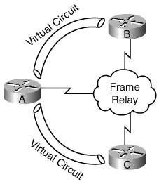
| Recall that routers work at the Open Systems Interconnection (OSI) model network layer, and that the main functions of a router are first to determine the best path that each packet should take to get to its destination, and second to send the packet on its way. To determine the best path on which to send a packet, a router must know where the packet's destination network is. Routers learn about networks by being physically connected to them or by learning about them either from other routers or from a network administrator. Routes configured by network administrators are known as static routes because they are hard-coded in the router and remain therestaticuntil the administrator removes them. Routes to which a router is physically connected are known as directly connected routes. Routers learn routes from other routers by using a routing protocol. Key Point A router uses a routing protocol to learn routes which it then puts in a routing table. A routed protocol is the type of packet forwarded, or routed, through a network.[4] IP is a routed protocol; this section explores routing protocols that can be used for IP. First, we examine ways in which routing protocols are classified. We then discuss the different metrics that routing protocols use to determine the best way to get to each destination network. This is followed by a discussion of how convergence time and the ability to summarize routes are affected by the choice of routing protocol. The final portion of this section describes the specific IP routing protocols. Classifying Routing ProtocolsYou can classify routing protocols in many ways. In the following sections, we describe four ways: interior versus exterior, distance vector versus link state versus hybrid, flat versus hierarchical routing, and classful versus classless routing. Interior and Exterior Routing ProtocolsAn autonomous system (AS) is a network controlled by one organization; it uses interior routing protocols, called interior gateway protocols (IGPs) within it, and exterior routing protocols, called exterior gateway protocols (EGPs), to communicate with other autonomous systems. Distance Vector, Link-State, and Hybrid Routing ProtocolsWhen a network is using a distance vector routing protocol, all the routers send their routing tables (or a portion of their tables) to only their neighboring routers. The routers then use the received information to determine whether any changes need to be made to their own routing table (for example, if a better way to a specific network is now available). The process repeats periodically. In contrast, when a network is using a link-state routing protocol, each of the routers sends the state of its own interfaces (its links) to all other routers (or to all routers in a part of the network, known as an area) only when there is a change to report. Each router uses the received information to recalculate the best path to each network and then saves this information in its routing table. As its name suggests, a hybrid protocol borrows from both distance vector and link-state protocols. Hybrid protocols send only changed information (similar to link-state) but only to neighboring routers (similar to distance vector). Key Point In summary, link-state protocols send small updates everywhere only when a change occurs, while distance vector protocols send larger updates periodically only to neighboring routers. Hybrid routing protocols send small updates only to neighboring routers and only when a change occurs. Link-state routers have knowledge of the entire network, while distance vector routers only know what their neighbors tell them. Routers running distance vector routing protocols typically send updates in broadcast packets, while those running link-state and hybrid routing protocols send the updates in multicast packets. Recall that broadcast packets are received and processed by all devices on a network, so even servers and PCs that have no need to see routing updates are interrupted by those sent in broadcast packets. In contrast, special multicast addresses are defined for each routing protocol that uses them. Only routers that are configured for that routing protocol and therefore need to receive the updates receive and process them; other devices are not interrupted. Routers running distance vector routing protocols have rules in place to help prevent routing loops. Key Point A routing loop occurs when packets bounce back and forth between routers because the routers are confused as to the best way to reach a destination network. These loops can occur if a network has changed but the routers have not yet all agreed on what the changed network looks like. One of these rules for distance vector routing protocols is known as the split-horizon rule. This rule states that if a router has a route in its routing table (in other words, if a router is using a route) that it learned through an interface, it must not advertise that route out of that same interface (even to a different device on that interface). This works fine unless the routing protocol is being used in a nonbroadcast multiaccess (NBMA) network, such as Frame Relay. In an NBMA environment, multiple routers are connected to each other using multiple virtual circuits on one interface. For example, in the network in Figure 3-11, when Router A learns a route from Router B, it wants to pass it to Router C. However, the split-horizon rule prevents it from doing this, because Router A has only one physical interface, connected to both Routers B and C. (You can find ways around this problem, including defining multiple virtual subinterfaces, one for each virtual circuit, on the physical interface.) Figure 3-11. The Distance Vector Split-Horizon Rule Prevents Router A from Passing Routes Learned from Routers B to C Distance vector routing protocols also use a hold-down mechanism to help prevent routing loops. When a router running a distance vector routing protocol receives information that a route to a destination has changed with the same or worse metric, it marks the route as being in a hold-down state; the new route is not put into the routing table until the hold-down timer expires, to give time for the other routers in the network to learn the new information. Flat and Hierarchical Routing ProtocolsFlat routing protocols have no way to restrict routes from being propagated within a major network (a Class A, B, or C network). In contrast, hierarchical routing protocols allow the network administrator to separate the network into areas and limit how routes are propagated between areas. This in turn reduces the routing table size and amount of routing protocol traffic in the network. Classful and Classless Routing ProtocolsRouting protocols can be categorized as classful or classless. Key Point Routing updates sent by a classful routing protocol do not include the subnet mask. Routing updates sent by a classless routing protocol include the subnet mask. Because classful routing updates do not come with a subnet mask, devices must assume what the subnet mask associated with a received route is. If a router has an interface in the same major network as the received route, it assumes the same mask; otherwise, it assumes the default mask, based on the class of the address. The IP address design implications of using a classful routing protocol are as follows:
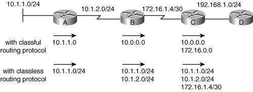
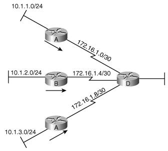
Figure 3-12 uses subnet addresses from three major networks. The upper portion of the figure illustrates routes sent through a network using a classful routing protocol. Router B assumes that the mask of the 10.1.1.0 route sent by Router A must be the same as the mask on the 10.1.2.0 subnet to which it is connected, because the mask is not sent along with the route. Router B summarizes all subnets of network 10.0.0.0 when it sends routing information to Router C because it is sending the route on an interface that is in a different major network. For the same reason, Router C summarizes network 172.16.0.0 when it sends routing information to Router D. Figure 3-12. Classful Routing Protocols Automatically Summarize on Major Network Boundaries; Classless Routing Protocols Do Not Have To Classless routing protocols include the subnet mask information with routing updates, so devices do not have to make any assumptions about the mask that is being used. Therefore, classless routing protocols support VLSMs, and subnets of the same major network can be discontiguous. Classless routing protocols also allow route summarization to be manually configured and to be turned off if it is automatic on the major network boundary. The lower portion of Figure 3-12 illustrates the routing information that could be sent when using a classless routing protocol. Figure 3-13 illustrates a discontiguous network. Three subnets of the major network 10.0.0.0 are allocated to the three LANs, and the three WANs are using subnets from the major network 172.16.0.0. If a classful routing protocol was used, Routers A, B, and C would all automatically summarize when sending routes to Router DRouter D would have three routes to network 10.0.0.0. Router D would therefore send traffic for any of the subnets of 10.0.0.0 to any of the other three routers, thinking that any of them can get to any of the available subnets; however, you can see from the topology that this is not true. Figure 3-13. Classful Routing Protocols Do Not Support Discontiguous Networks; Classless Routing Protocols Do Instead, if a classless routing protocol is used, the following could be configured on the routers:
Router D could then send traffic for destinations on the three subnets to the correct router. MetricsOne of a router's jobs is to determine the best path to each destination network. The routing protocol metric is the value that the routing protocol uses to evaluate which path is best. Metrics can include the following factors:
Some routing protocols use a composite metric, which is a combination of various factors. For example, IGRP and EIGRP use a metric that can include the bandwidth, delay, load, and reliability of the path. (However, by default, these protocols only use the bandwidth and delay in their metric calculations, as described in the "Routing Protocol Comparison" section, later in this chapter.) Key Point A lower metric value indicates a better path. For example, a path with a hop count of 2 is preferred over a path with a hop count of 5. Note, however, that comparisons can only be made between the same metric type; for example, you cannot compare a hop count of 2 to a cost of 10. On Cisco routers, all IP routing protocols support equal-cost (or equal-metric) load balancing, the ability to keep multiple paths, with the same metric, to the same destination network, and balance (or share) the load between those paths. By default, Cisco routers can keep up to four equal-cost paths and can be configured to keep up to six such paths. Convergence TimeKey Point A network is converged when the routing tables in all the routers are synchronized so that they all contain a usable route to every available network. Convergence time is the time it takes all the routers in a network to agree on the network's topology, after that topology has changed. Network design impacts convergence time significantly; in fact, proper network design is a must, or else the network might never converge.[5] Other factors that affect the convergence time include the routing protocol used, the size of the network (the number of routers), and various configurable timers. For example, consider the type of routing protocol used. Assuming a proper design, link-state routing protocols usually converge quicker than distance vector routing protocols, because they immediately send the change to all other routers. Link-state routing protocols have a timer that prevents them from calculating the new routes immediately (so that many changes can be incorporated into one calculation); thus, they tend to converge within a few seconds. Distance vector algorithms send updates periodically (every 30, 60, or 90 seconds is typical), so you might think that it takes a long time for changes to propagate. Fortunately, the distance vector routing protocols in use today are usually more intelligent and send flash updates. Flash updates, also called triggered updates, are sent as soon as something changes so that the routers are notified quickly. However, another mechanism prevents these routing protocols from converging fastthe hold-down mechanism (to prevent routing loops). When a router running a distance vector routing protocol receives information that a route to a destination has changed with the same or worse metric, it marks the route as being in a hold-down state; the new route is not put into the routing table until the hold-down timer expires. The hold-down timer is typically set to three times the periodic update timer; this gives time for the other routers in the network to learn the new information. Note, however, that a route in the hold-down state is still used to forward traffic. Therefore, if a link goes down and then comes up before the hold-down timer expires, it will be reachable. If the link remains down for the hold-down period, though, the router connected to the link will reply to any packets destined for devices on the link with an error message. EIGRP is a hybrid routing protocol; it therefore has different convergence characteristics. EIGRP does not use periodic updates or hold-down timers; it does send flash updates to its neighboring routers, but only when necessary. EIGRP not only keeps the best routes in its routing table, but it also keeps all the routes to all destinations in another table, called a topology table. If the best route to a destination goes down, a router running EIGRP simply has to get the next-best route from the topology table, if one exists, and put it in its routing table; thus EIGRP can converge extremely fast. The router only has to talk to its neighboring routers if a suitable next-best route in its topology table doesn't exist. This can occur, for example, if the downed link has resulted in a significant change in the network, or if specific routes are no longer reachable through any paths. Note The "Routing Protocol Comparison" section, later in this chapter, details the operation of each IP routing protocol. Route SummarizationThe routing protocol choice affects summarization. As noted in the "Classful and Classless Routing Protocols" section earlier in this chapter, classful routing protocols automatically summarize on the major network boundary; this automatic behavior cannot be turned off. Some classless routing protocols also automatically summarize, but do allow summarization to be turned off and also allow summarization to be turned on at other boundaries. Routing Protocol ComparisonThe following routing protocols can be used for IP:
Table 3-2 shows where these routing protocols fit in the various categories discussed earlier in this chapter. Each of the routing protocols is further described in the following sections. Later in this chapter, the "IPv4 Routing Protocol Selection" section describes how to choose which routing protocols you should use in your network, and what you need to consider if you decide to use more than one routing protocol.
Routing Information Protocol, Versions 1 and 2RIP is the original IP distance vector routing protocol. RIPv1 is classful and RIPv2 is classless. RIP's metric is hop count; for each destination, it selects the path with the least number of routers. The hop count is limited to 15, so RIP is only suitable for small networks. RIPv1 is not as popular as it once was. However, RIPv2 can still be used for small networks. The main advantage of using RIP is its simplicity, as explained in the following list:
Both RIPv1 and RIPv2 automatically summarize at the major network boundary; RIPv2 allows this functionality to be turned off, so it supports discontiguous addressing. Other RIPv2 improvements over RIPv1 include its support for VLSMs, its use of multicast rather than broadcast for sending routing updates, and its support for authenticating routing updates to ensure that routes are only exchanged with authorized routers. The main disadvantages of using RIP are its slow convergence (because it is a distance vector routing protocol) and the fact that it only uses hop count as its metricit selects the path with the least number of routers to the destination, without regard to the speed of the links on the path. For example, RIP would choose a route that is two hops through a slow WAN connection rather than going three hops over Ethernet. RIP's snapshot routing feature allows it to be used on a dial-up network. This feature allows the router on each side of the connection to take a snapshot of the routing table while the link is up, and use that snapshot to update any other routers on its side of the connection while the link is down. The link is only brought up when necessary, for example, when data needs to be sent across itduring that time, the routing table can be updated. Interior Gateway Routing ProtocolIGRP is a Cisco-proprietary routing protocol developed by Cisco to include many improvements over RIP. As a classful distance vector routing protocol though, IGRP has relatively slow convergence, does not support VLSMs, and automatically summarizes routes at the classful network boundary. The distance vector split-horizon feature also restricts its ability to work on NBMA networks, such as Frame Relay. However, IGRP's metric provides a more useful gauge of a path's suitability in most networks. IGRP uses a composite metric, with bandwidth, delay, load, and reliability all factored into the metric equation. Some constants are used in the metric calculation; with their default values, the IGRP metric formula is as follows: metric = bandwidth + delay The terms in this formula are defined as follows:
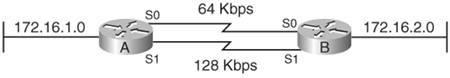
Note The hop count and the maximum transmission unit (MTU) are also carried along with IGRP routing updates. The MTU is the maximum packet size that can be sent without fragmentation. A lower metric value indicates a better pathfaster with the least amount of delay. IGRP allows the network to be divided into what it calls autonomous systems, although this is a different use of the term than in the previous discussion of interior and exterior routing protocols. You can think of IGRP's use of the term as being similar to groups: You can have different groups of routers running IGRP, and routing information is not shared among the groups unless you explicitly configure the routers to do so. For example, if your network is running IGRP and your organization acquires another organization that is also running IGRP, you might want to keep the two networks separate initially, and just share specific routes. The autonomous system numbers allow this to be accomplished easily. Another feature introduced in IGRP is the ability to load-balance, or load-share, over unequal-cost paths, not just over equal-cost paths, as other routing protocols can do. For example, consider the network shown in Figure 3-14. From Router A's perspective, network 172.16.2.0 can be reached in two waysthrough the serial 0 (S0) interface at 64 kbps or through the serial 1 (S1) interface at 128 kbps. Ordinarily, the 128-kbps link would be chosen as the preferred path because it is faster, and all traffic would flow over that link. The 64-kbps link would not be used (unless and until the faster link became unavailable). IGRP allows unequal-cost load balancing so that traffic can flow across both links, in proportion to their speed. This makes better use of the available bandwidth. Figure 3-14. GRP (and EIGRP) Can Load-Balance over Both Equal- and Unequal-Cost Paths Like RIP, IGRP is easy to configure and troubleshoot. However, because of its classful distance vector behavior, IGRP is seldom used in today's networks; EIGRP is a better choice because it retains all of IGRP's advantages and overcomes its disadvantages. In fact, Cisco will be discontinuing IGRP in future software releases, and recommends EIGRP in its place.[7] Note Cisco has made it easy to change from running IGRP to EIGRP on a network. The conversion can be made gradually, because routes between the two routing protocols are automatically shared if the same autonomous system number is used when configuring both protocols. Enhanced Interior Gateway Routing ProtocolEIGRP, as its name indicates, is an enhanced version of IGRP and is also Cisco-proprietary. EIGRP is a classless hybrid routing protocol that combines the best features of distance vector and link-state routing protocols. EIGRP performs well on LANs and WANs, including in NBMA environments; unlike distance vector routing protocols, EIGRP's split-horizon feature can be turned off if necessary for use on an NBMA network. Note EIGRP is not appropriate for use on a dial-up network because it maintains the relationship with its neighboring routers by sending hello messages periodically. Doing this on a dial-up connection would mean that the link would have to remain up all the time. EIGRP can be used to route not just IP but also Internetwork Packet Exchange (IPX) and AppleTalk routed protocols. Each of these routed protocols is handled completely independently. In this book, we only discuss the operation of EIGRP with respect to IP. As a classless routing protocol, EIGRP supports VLSMs. It automatically summarizes on the classful network boundary, but this summarization can be turned off and summarization can be done at any other boundary in the network, by any of the EIGRP routers. This allows a hierarchical topology to be supported. Although this is good design practice, it is not required by EIGRP. EIGRP is based on the Diffusing Update Algorithm (DUAL), which provides its very fast convergence. The following list of EIGRP terms helps to explain how EIGRP operates:
EIGRP routers exchange routes only with their neighboring routersneighbor relationships are established and maintained with periodic, small, hello messages. Routing updates are only sent when a change occurs, and only the changed information from the routing table is sent. All EIGRP messages use multicast, rather than broadcast, to reduce interruptions of other network devices. When an EIGRP router learns that a path it was using in its routing table (a successor route) has gone down, it looks in its topology table to see whether a usable backup route is available, through a feasible successor. If a route is available, the router copies that route to its routing table and starts using itno further calculation or communication with other routers is required. As mentioned earlier, this can result in extremely fast convergence after a change in the network. An EIGRP router only has to send query messages to its neighborstrying to find alternate routes to the destination now that the network has changedif it doesn't have a suitable backup route in its topology table.
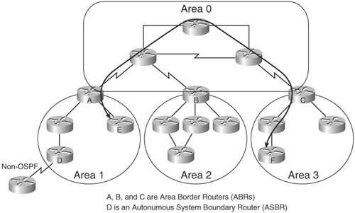
The DUAL algorithm uses the same metric calculation as that used by IGRP, but the value is multiplied by 256 for EIGRP (because EIGRP uses 32 bits, instead of IGRP's 24 bits, for the metric). EIGRP, like IGRP, supports both equal- and unequal-cost load balancing. EIGRP uses much less bandwidth than IGRP because it only sends the routing table entries that have changed only when a change occurs, rather than sending the entire table periodically. The bandwidth used by the periodic hello messages can be a concern on slower WAN links with many neighbors (as can occur on an NBMA network), but normally this is not an issue. EIGRP, like IGRP, is easy to configure. It uses the same autonomous system numbers as IGRP, and in fact can automatically share information with IGRP routers configured with the same autonomous system number. No special configuration is required for different types of Layer 2 media (as is the case for OSPF, as described in the next section). Open Shortest Path FirstOSPF is a standard (not Cisco-proprietary) routing protocol, developed to overcome RIP's limitations. As a classless link-state routing protocol, it supports VLSMs and convergences quickly. Note The latest version of OSPF for IPv4, OSPF version 2, is described in RFC 2328, "OSPF Version 2." OSPF requires a hierarchical design. The OSPF network is called a domain or an autonomous system and is divided into areas. One backbone area exists, area 0, to which all other areas must be connected and through which all traffic between other areas must flow. Figure 3-15 illustrates an OSPF network. Traffic between Routers E and F in this figure, for example, must flow from area 1 through Router A, through the backbone area 0, and then into area 3 through Router C. (Even if another physical link existed between the routers in these areas, it could not be used.) Figure 3-15. Traffic Between OSPF Areas Must Go Through the Backbone Area 0 The routers that are on the boundary between area 0 and another area are called Area Border Routers (ABRs); Routers A, B, and C in Figure 3-15 are ABRs. ABRs are responsible for passing traffic to and from the backbone. Routers that are the interface between the current OSPF domain and other domains (for example, using static routes) are called Autonomous System Boundary Routers (ASBRs). Router D in the figure is an ASBR. The ASBR takes care of exchanging routing information between the current OSPF domain and the external domain. An OSPF router communicates and maintains relationships with other routers using a hello protocol, similar to the one used by EIGRP. OSPF routing updates are sent in link-state advertisements (LSAs), describing the state of links (interfaces); LSAs are sent in multicast packets called link-state updates (LSUs). An OSPF router exchanges LSAs about all its links with all the routers in its area so that all routers in an area have the same information. Each router puts this information in its topology table and then runs the shortest path first (SPF) algorithm to calculate its shortest path to each destination network. These shortest paths are put in the routing table. Different types of LSAs are sent, depending on the type of router (ABR, ASBR, and so on) that is sending the advertisement. An OSPF router sends an LSA whenever it detects a change; this can result in a lot of bandwidth being used if the network is not stable. OSPF routers receive LSAs and run the SPF algorithm whenever a change occurs in the network. Timers ensure that OSPF waits for a few seconds after receiving an LSA before running SPF so that multiple changes can be incorporated into one SPF calculation. This helps to limit the resources used by OSPF, but it also means that the convergence time is increased. Note The OSPF incremental SPF feature, introduced in Cisco Internet Operating System (IOS) Release 12.0(24)S, allows OSPF to converge faster when a network topology changes. Information on this feature is available in the "OSPF Incremental SPF" document.[9] OSPF routers do not automatically summarize routes. By default, all routing information is sent to all OSPF routers in the domain, although it might be sent in a different LSA type. Manual summarization can be configured, but only on ABRs and ASBRs. Thus, a sound IP addressing design is important, to ensure that the ABR can summarize routes so that the routing protocol traffic between areas is kept to a minimum. OSPF also supports defining different types of areas to limit the amount of routing traffic passing into areas. For example, on Cisco routers an OSPF area can be configured as a totally stubby area so that only a default route is passed into the area; traffic for any destinations external to the area is sent out on the default route. This configuration is useful for areas that do not connect to non-OSPF networks. The routers within the area then only have to keep minimal routing information, but can still get to all destinations. OSPF treats different Layer 2 media differently, and special configuration is required for some Layer 2 media. For example, OSPF can run on NBMA networks, but it requires special configuration to do so. For use over dial-up links, an OSPF feature called demand circuit (DC) can be configured; it suppresses the hello messages. The metric used by OSPF is called the cost, and it is inversely proportional to the bandwidth of the interfacein other words, slower links have a higher cost. On Cisco routers, the default cost calculation is as follows: Cost = Reference bandwidth in Mbps / Bandwidth The default reference bandwidth is 100 Mbps. The bandwidth in this formula is the bandwidth defined on the interface, which can be configured differently than its default. Using the default reference bandwidth value in the formula assumes a maximum bandwidth of 100 Mbps (resulting in a cost of 1). You can change the reference bandwidth value on the routers in the network if you have faster interfaces (it should be set to the same value on all routers to ensure a consistent calculation). You can also manually set the cost on each interface. OSPF does not limit the number of hops that a routing update can travel in the network. In "Designing Large-Scale IP Internetworks,"[10] Cisco recommends the following guidelines:
These values are recommended to ensure that OSPF calculations do not overwhelm the routers. Of course, the network design and link stability can also affect the load on the routers. Integrated Intermediate System-to-Intermediate SystemIntegrated IS-IS is a link-state classless routing protocol that has the following similarities with OSPF:
Note Integrated IS-IS is defined in RFC 1195, "Use of OSI IS-IS for Routing in TCP/IP and Dual Environments." Many differences also exist between the two protocols. The main difference relates to the fact that IS-IS is the routing protocol for the OSI protocol suite, specifically to route Connectionless Network Protocol (CLNP) data. CLNP is a routed protocol of the OSI suite, just as IP is the routed protocol for the TCP/IP suite. Integrated IS-IS is an extended version of IS-IS used for IP. Recall that EIGRP also supports multiple routed protocols (IP, IPX, and AppleTalk); with EIGRP, each of these routed protocols is handled independently. With Integrated IS-IS, the IP routing information is included as part of the CLNP routing information. Therefore, OSI protocol suite addresses must be configured even if IS-IS is only being used for routing IP. OSI protocol suite addresses, which are a maximum of 20 bytes long, are called network service access points (NSAPs). Each device, rather than each interface, has an address. Although Integrated IS-IS is used extensively by ISPs, OSI addresses are not widely understood, and therefore this routing protocol is not widely used outside of ISPs. Another difference between IS-IS and OSPF is how areas are defined and used. The following OSI terminology and Figure 3-16 help to explain how Integrated IS-IS operates:
Figure 3-16. Integrated IS-IS Level 2 and Level-1-2 Routers Form a Contiguous Backbone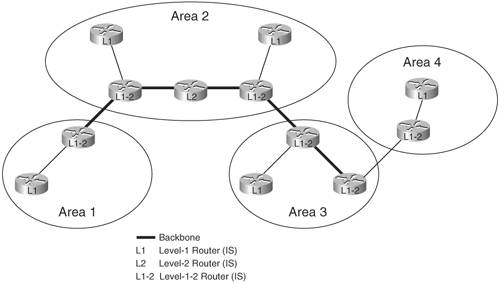 Notice that the edge of an IS-IS area is on a link, rather than inside of a router, as is the case for OSPF. Also notice that it is easy to extend the IS-IS backbone and add on more areas. You just need to configure a router as L2 or L1-2 and connect it to another L2 or L1-2 router, and it is part of the backbone. This flexibility means that IS-IS is much easier to expand than OSPF. IS-IS also sends out less update packets than OSPF, resulting in less traffic and therefore allowing more routers per area. IS-IS routes can only be summarized by L1-2 routers as they are sent into Level 2. All L1-2 routers in an area should perform the same summarization so that the other areas see only the summary routes; otherwise, traffic will flow to the router that is not summarizing, because it advertises more specific routes. Note If more than one entry in the routing table matches a particular destination, the longest prefix matchthe most specific route that matchesin the routing table is used. Several routes might match one destination, but the one with the longest matching prefix is used. Integrated IS-IS does not inherently support NBMA point-to-multipoint networks; in this case, multiple subinterfaces must be used to create multiple point-to-point networks. IS-IS on Cisco routers assigns all interfaces a metric value of 10; it does not take into account the bandwidth of the link. This obviously is not appropriate in networks with varying link speed; in fact, it behaves similar to RIP's hop count metric. The metric for IS-IS can be changed manually on each interface, and should be done so for proper routing behavior. Border Gateway Protocol Version 4BGP4 is the exterior routing protocol, the EGP, for the TCP/IP suite and is used extensively throughout the Internet. BGP is based on distance vector operation and uses a path vector as its metric. A path vector is a set of attributes of a path to a destination, including a list of AS numbers that the path goes through. The number of autonomous systems in this list can be thought of as being similar to a hop count, and can be used to affect the choice of which path is considered to be the best. BGP is needed if an organization has more than one Internet connection and needs to determine which information should flow through each connection. BGP is also required if the AS allows packets to transit through it, from one AS to another AS; in this case, it is called a transit AS. An ISP is an example of a transit AS. Another reason to use BGP is if the AS must manipulate the flow of traffic entering or leaving the AS. In this latter case, BGP is being used as a policy-based protocolpolicies can be defined to affect the way traffic flows through the AS. In BGP, each AS is assigned an AS number. AS numbers are 16 bits, with values from 1 to 65535. Private AS numbers are 64512 through 65535; these are much like the private IP addresses and are not to be used on the Internet. (We only use private AS numbers in this book, just as we only use private IP addresses.) BGP uses TCP to communicate. Any two routers that have formed a TCP connection to exchange BGP routing informationin other words, that have formed a BGP connectionare called BGP peers or neighbors. BGP peers can be either internal or external to the AS. When BGP is running between routers within one AS, it is called internal BGP (IBGP). IBGP exchanges BGP information within the AS so that it can be passed to other autonomous systems. As long as they can communicate with each other, routers running IBGP do not have to be directly connected to each other. For example, if EIGRP is running within the AS, the routers will have routes to all destinations within the AS; they use this EIGRP routing information to send the BGP information to the routers that need it. You can think of IBGP running on top of the interior routing protocol (EIGRP in this example)it uses the interior routing protocol to send its BGP information. When BGP is running between routers in different autonomous systems, it is called external BGP (EBGP). Routers running EBGP are usually connected directly to each other. Note Understanding BGP operation is crucial to implementing it successfully. Many BGP parameters can be changed, and many BGP features can be configuredconfiguring and troubleshooting BGP can be complex. Because BGP typically involves connections to the Internet, errors can be catastrophic. BGP4 is a classless routing protocol, so both the route and the prefix information are included in the routing updates. Thus, BGP4 supports VLSMs. It also supports classless interdomain routing (CIDR) addressingblocks of multiple addresses (for example, blocks of Class C addresses) can be summarized, resulting in fewer entries in the routing tables. |

EAN: 2147483647
Pages: 156