17.2 Boundary Hatching
|
| < Day Day Up > |
|
The Boundary Hatch dialog box (Figure 17.2a - next page), accessed by the BHatch command, provides user-friendly access to many of the Hatch command options. It also offers some major benefits that the Hatch command doesn't. Let's take a look at the dialog box.
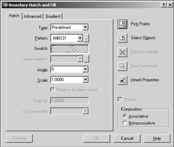
Figure 17.2a
The first tab you see (Hatch) allows you to set up the Type, Pattern, Scale, and Angle of desired hatching. Simply put, it does most of the things you did on the command line but with an easier interface.
The second tab (Advanced) enables you to determine how the hatching will be applied (Normal, Outermost, Ignore, and a few other options).
The third tab (Gradient) is new to the 2004 release. It allows you to create some interesting gradient fills - similar to the solid option but with more clout.
Additionally, you'll find a series of buttons down the right side of the dialog box. The first four buttons allow you to identify where the hatch pattern will go. The fifth is sort of a cheater to set the properties on the Hatch tab a little faster.
Let's take a more detailed look at the Boundary Hatch dialog box.
-
We'll start with the Hatch tab.
-
The Type control box allows you to select a Predefined pattern, a User-defined pattern, or a Custom pattern.
-
The Predefined patterns accompany AutoCAD. You can see samples of these in the Swatch box or by picking the button next to the Pattern control box.
-
The User-defined option allows you to set the Angle and Spacing of lines (using control boxes), and to decide whether or not to Double the pattern as you did in the last exercise. The Spacing text box and the Double check box are only available when the User- defined option has been selected. These correspond to their Hatch command counterparts.
-
Selecting Custom in the type control box allows you to select a custom pattern. A custom pattern is also predefined, but the definition is stored in a file other than the Acad.pat (the file where AutoCAD keeps hatch pattern definitions by default). The CAD guru will provide custom patterns if needed. If the Custom option is selected in the Pattern control box, you must enter the name of the desired pattern in the Custom Pattern control box.
-
-
The Pattern control box allows you to scroll through the patterns one at a time; or you can pick the button to the right of the control box to display the Hatch Pattern Palette dialog box, which displays several patterns at a time.
-
Scale and Angle control boxes are provided for you to set these options as you did at the Hatch command prompt.
-
The ISO Pen Width option is only available when an ISO pattern has been selected. This control box allows you to select the width of the ISO lines.
-
-
The Advanced tab (Figure 17.2b) offers you some choices in how to apply the hatching.
-
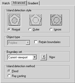
Figure 17.2b-
In the Island detection style frame, you find the same three styles you used on the command line. But thanks to the dialog box format, you can see samples of each.
-
The Object type and Boundary set frames work together. Let me explain.
You'll notice that, in larger drawings, it may take AutoCAD a while to locate boundaries when using the Pick Points method. This is because AutoCAD must search the drawing database for information on all visible objects. Using the New button in the Boundary set frame can really hasten this process. When picked, AutoCAD will prompt you to Select objects on the screen, and then return to the Advanced tab of the Boundary Hatch dialog box. AutoCAD will then restrict its search to the objects selected. You can make the new boundary set from the Current viewport or from an Existing Set by selecting your choice from the control box in the Boundary set frame.
When defining a new boundary set, you should use a window or crossing window; other methods will work, but these are faster in a large drawing. In the Object type frame, you can tell AutoCAD to retain the defined area as a polyline or a region (an object similar to a 2-dimensional solid). Simply place a check in the Retain boundaries box and then make your selection in the control box in the Object type frame.
Note The tools available in the Object type and Boundary set frames can make a tremendous difference in the amount of time required for AutoCAD to hatch objects in larger drawings. However, you must decide if it's necessary to use these tools by considering how long you're willing to wait for the hatching and how long AutoCAD is taking to do the job.
-
The last frame - Island detection method - is a bit deceiving. What it boils down to is simply: Do you want AutoCAD to detect islands (boundaries within boundaries) or not? If you do, leave the bullet next to Flood; if you don't, move the bullet to the Ray casting option.
-
-
The greatest benefit to creating hatch patterns using the Hatch command (that isn't available using the BHatch dialog box) is the direct hatch option. This is an ideal tool for adding partial grating to platforms and walkways, or adding partial façade features (such as brickface) to a building elevation. Use this when you just need a sample of the pattern or when fully hatching an area might hinder the clarity of the drawing.
-
The third tab - Gradient (Figure 17.2c) - allows you to apply a color or colors with graduated intensity; that is, you can create colors that get more or less intense from one part of the colored area to another.
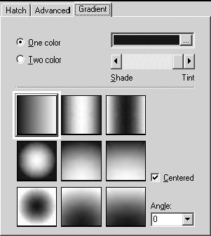
Figure 17.2c-
You can select between a One color or a Two color gradient with the radio buttons at the top of the tab. If you opt for one, AutoCAD presents a color selection box (to the right of the radio buttons) and a Shade/Tint slider bar to help you control the intensity of the color. If you opt for two colors, AutoCAD replaces the Shade/Tint slider bar with a second color selection box to allow you to select the second color.
(You can control the intensity of the colors from the Select Color dialog boxes presented by the color selection box buttons.)
-
In the lower half of the box, AutoCAD presents nine selections for how you'd like your gradient to behave. Select the one you prefer.
-
The Centered check box controls how the graduations behave - remove the check and the intensity grows from mild in the upper left corner (appearing something like a light source) to more intense as you move away from the upper left corner.
-
The Angle selection box, of course, controls the angle of the gradients.
-
-
Once you've made your selections on the tabs, you must tell AutoCAD what to hatch using one of the buttons on the right side of the dialog box.
-
You can find one of the greatest enhancements to hatching (and one of my personal favorites) in the Pick Points button. With this nifty tool, you simply pick a point where you want hatching. AutoCAD fans outward from that point to find the nearest boundaries. You just can't get any simpler than this. (Again, you must be sure that you select inside a closed area.)
-
The Select Objects button allows you to select objects just as you did at the command line in the last exercise.
-
Remember how the Normal style worked? AutoCAD hatched between the outer two boundaries, skipped hatching between the next two boundaries, hatched between the next two, and so forth. AutoCAD recognizes boundaries within the outermost boundary as islands and adjusts the hatching for clarity. The same holds true when you select the boundary using the Pick Points button. You can use the Remove Islands button to tell AutoCAD to ignore the islands and hatch over them. But the Remove Islands button give you more control over which islands to ignore.
-
The View Selections button highlights the currently selected boundaries to help you verify the selection.
-
Use the Inherit Properties button when you don't know the style of pattern you want to match. That is, when you've used several styles in a drawing and wish to duplicate the settings of one of them, pick this button. AutoCAD will ask you to select the style you want to duplicate. It'll then reset the Boundary Hatch dialog box options to match that style. (How's that for handy?)
-
The Preview button (lower left corner of the dialog box) allows you to see the hatched object before completing the command. This way, you can make any necessary adjustments before applying the hatching.
-
The Composition frame in the lower right quadrant of the dialog box gives you the chance to use Associative hatching. This means that hatch patterns will update automatically when the boundaries change. This option isn't available at the command line.
You can also tell AutoCAD to draw hatch lines as individual objects (Nonassociative - or pre-exploded). (This option is available at the command line by placing an asterisk (*) in front of the name of the hatch pattern - as in *ANSI31.) But be aware that exploded hatch patterns dramatically increase the size of a drawing and the amount of work involved in modifying the pattern. If you don't create the pattern already exploded, you can always explode the pattern (using the Explode command) just as you could explode a polyline.
-
Let's take a look at hatching using the Boundary Hatch dialog box.
| Note | In addition to the command line and toolbars, selecting Hatch under the Draw pull-down menu will access the BHatch command. |
Do This: 17.2.1 Hatching with a Dialog Box
-
Be sure you're still in the demo-hatch.dwg file the C:\Steps\Lesson17 folder. If not, please open it now.
-
Follow these steps.
TOOLS
COMMAND SEQUENCE
STEPS

Hatch Button
Command: h
1. Open the Boundary Hatch dialog by entering the BHatch command - type bhatch, bh, or h at the command prompt. Alternately, you can pick Hatch button on the Draw toolbar.
2. On the Hatch tab, pick the Pattern button. The Hatch Pattern Palette dialog box appears (Figure 17.2.1.2a).
Here you can select a pattern in one of two ways:
-
double-click on it;
-
click on the desired pattern and then pick the OK button.
Pick the tabs and use the scroll bar to see other patterns.
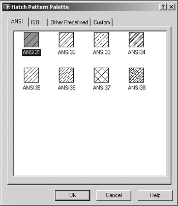
Figure 17.2.1.2a
3. Double-click on the ANSI33 pattern (first tab, first row, third column). AutoCAD returns to the Boundary Hatch dialog box. The ANSI33 pattern is now shown as current in the Pattern and Swatch control boxes.
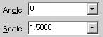
4. Set the Scale to 1.5 and the Angle to 0.

5. Pick the Advanced tab.
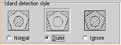
6. Set the Style to Outer in the Island detection style frame.

Pick Points Button
7. Pick the Pick Points button. AutoCAD returns to the graphics screen and prompts to Select internal point.
Select internal point:
8. Pick any point between the rectangle and the polygon.
Selecting everything...
Selecting everything visible...
Analyzing the selected data...
Analyzing internal islands...
Select internal point:
9. AutoCAD tells you what it's doing, and then repeats the prompt. Right-click to display the cursor menu.
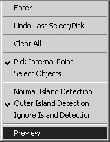
10. We could return to the Boundary Hatch dialog box and pick the Preview button to see the hatching before applying it. But let's use the Preview option on the cursor menu.
Your drawing looks like Figure 17.2.1.10a.
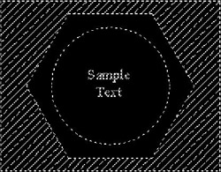
Figure 17.2.1.10a: Preview of HatchNote Note: The Preview Hatch display isn't always accurate. Most of the ANSI patterns preview fairly well; but many of the other, more complex patterns tend to lose definition or not display at all. If the pattern doesn't display, but you're reasonably sure of your settings, go ahead and apply the pattern. You can always edit or erase the pattern and start again.
<Previewing the hatch>
Pick or press Esc to return to dialog or <Right-click to accept hatch>:
11. Hit the Esc button return to the dialog box.

12. Pick the OK button to complete the command. AutoCAD returns to the graphics screen and the command prompt. Your drawing looks like Figure 17.2.1.12a.
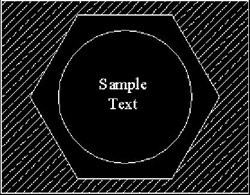
Figure 17.2.1.12a
Command: h
13. Repeat Steps 1 through 15, but hatch between the polygon and the circle with the ANSI37 pattern. Use a Scale of 2.0 and an Angle of 45°. Your drawing will look like Figure 17.2.1.13a.
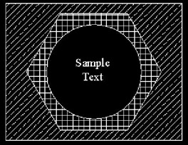
Figure 17.2.1.13a
Command: [enter]
14. Now we'll use the Inherit Properties button to hatch the circle using the ANSI33 pattern we used between the rectangle and the polygon. Repeat the BHatch command. Notice that the settings default to the last settings used.

Inherit Properties Button
15. Pick the Inherit Properties button. AutoCAD returns you to the graphics screen and prompts Select associative hatch object.
Select associative hatch object:
16. Pick a line on the hatch pattern between the rectangle and the polygon.
Inherited Properties: Name <ANSI33,_O>, Scale <1.5000>, Angle <0>
Select internal point:
17. Pick a point inside the circle.
Selecting everything...
Selecting everything visible...
Analyzing the selected data...
Analyzing internal islands...
Select internal point: [enter]
18. Hit enter. AutoCAD returns to the Boundary Hatch dialog box. Notice that the settings have changed to match those used when you created the first hatching.
19. Change the Angle setting to 90°.

View Selections Button
20. Pick the View Selections button. AutoCAD returns to the graphics screen and highlights the boundaries you selected in the previous step.
<Hit enter or right-click to return to the dialog>
21. Hit enter (or right-click) to return to the Boundary Hatch dialog box.

22. Preview the hatching if you wish, then OK it. Your drawing looks like Figure 17.2.1.22a.
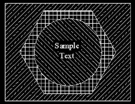
Figure 17.2.1.22a
Command: s
23. Now for a real treat, try stretching the rectangle or the polygon. Note the effects of Associative hatching!

Command: qsave
24. Undo the Stretch command and save the drawing.
-
So, which do you prefer - the command line approach or the Boundary Hatch dialog box?
You probably think the dialog box is more user- friendly; and you're right. The Pick Points button makes a lot of difference when you're in a hurry or having difficulty selecting boundary objects. (But you can still use the Select Objects button to emulate the command line approach.) And you shouldn't underestimate the value of seeing a pattern before selecting it. You may still run into the same problems with boundaries that aren't quite closed or patterns that seem to bleed outside the boundaries. But if you do, use the command line and the direct hatch option.
We're going to take a look at one more thing in the Boundary Hatch dialog box - the Define Boundary Set option - to wrap up the two traditional approaches to hatching. But, as those infuriatingly irritating commercials so often repeat, don't order yet! There are a couple tricks to hatching that just might make you foreswear the traditional!
Let's look at the Define Boundary Set option first.
Do This: 17.2.2 Boundary Sets
-
Open the zk147_2.dwg file the C:\Steps\Lesson17 folder. The drawing looks like Figure 17.2.2a.
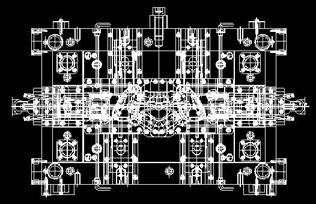
Figure 17.2.2a: This material has been reprinted with the permission of and under the copyright of Autodesk, Inc. This reproduction is provided with RESTRICTED RIGHTS. Use, duplication or other disclosure by the US government is subject to restrictions set forth in FAR 52.227-19 (Commercial Computer Software-Restricted Rights) and DFAR 252.227-7013(c)(1)(ii) [rights in -
Follow these steps.
TOOLS
COMMAND SEQUENCE
STEPS

1. Occasionally, you'll run into a drawing that opens on one of the Layout tabs (as this one does). We'll work on a Model tab, just as we've done since we began this text. This is a good chance to see how to switch back to "Model Space" - simply pick on the Model tab below the graphics area.
Command: z
Specify corner of window, enter a scale factor (nX or nXP), or
[All/Center/Dynamic/Extents/ Previous/Scale/Window] <real time>: 170,620
Specify opposite corner: 800,40
2. Zoom into the lower left portion of the drawing as indicated (coordinates are approximations).

Command: h
3. Open the Boundary Hatch dialog box.
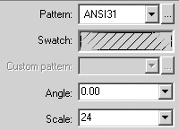
4. Use the default Pattern and Angle, but change the Scale to 24 (the scale factor for this drawing).
Select internal point: Selecting everything...
Selecting everything visible...
5207 selected,
Do you really want to do this? <N> y
Analyzing the selected data...
Analyzing internal islands...
Select internal point:
Analyzing internal islands...
Select internal point: [enter]
5. Use the Pick Points button to hatch the areas indicated in Figure 17.2.2.5a (lower left quadrant of your screen). When prompted as shown, enter y.
Pay close attention to how long it takes AutoCAD to find the boundaries.
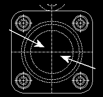
Figure 17.2.2.5a
6. Complete the command. (Regenerate the drawing if necessary to see the hatching.)

Command: h
7. Now we'll see a faster way. Repeat the BHatch command.

8. Pick the Advanced tab to display the Advanced options.

New Boundary Button
9. Pick the New button in the Boundary Set frame. AutoCAD returns to the graphics screen and prompts you to Select objects.
Select objects: 190,320
Specify opposite corner: 290,85
Select objects: [enter]
Analyzing the selected data...
10. Place a window as indicated. Then hit enter to complete the selection. AutoCAD returns to the Boundary Hatch dialog box.

Select internal point:
Analyzing internal islands...
Select internal point:
Analyzing internal islands...
Select internal point: [enter]
11. Use the Pick Points method to hatch the areas indicated in Figure 17.2.2.11a. Pay close attention to how long it takes AutoCAD to find the boundaries this time.
Figure 17.2.2.11a
12. Did you notice the difference? Which was faster?
Complete the command.
Command: quit
13. Exit the drawing without saving.
Novice operators frequently overlook this last technique - especially if they work on smaller drawings where boundary sets aren't needed. But if you're going to be working on drawing larger than half a megabyte, it's a good idea to become comfortable with this approach to hatching.
|
| < Day Day Up > |
|
EAN: 2147483647
Pages: 96