2.2 Evolution of integrated receiver architectures
|
2.2 Evolution of integrated receiver architectures
2.2.1 The conventional superhet architecture
The superhet receiver has long been the default architecture of choice for the vast majority of applications. Moving the wanted signal to a fixed, intermediate frequency (IF) exchanges the difficult problem of making a tuneable channel filter for the generally rather easier one of making a tuneable local oscillator (LO). However, there is an issue with the so-called image signal which appears at a frequency on the opposite side of the LO and which needs to be removed with an RF filter before the mixer. When the wanted signal is at a high frequency and the channel bandwidth is narrow, it can be impossible to identify a single IF that allows a practical realisation of the RF and channel filters with the required degree of selectivity. Hence, as shown in Figure 2.1, there is often a need to use more than one IF to achieve the necessary receiver performance.
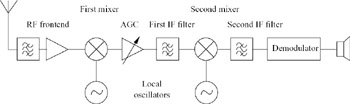
Figure 2.1: Conventional superhet architecture
The superhet can offer excellent sensitivity and selectivity. However, its intrinsic reliance on highly selective, passive, analogue, off-chip filters usually makes it comparatively bulky and expensive to implement. It also tends to rely heavily on the use of automatic gain control (AGC). These are all serious impediments to multimode operation. There is also little scope for addressing this issue by increasing the level of digitisation as the analogue-to-digital conversion (ADC) would have to take place very late in the receiver chain, leaving most of the signal processing in the analogue domain.
2.2.2 The zero-IF architecture
The zero-IF receiver [1] has obvious merits but it is only recently that it has been widely used for applications calling for good performance. By shifting the IF to zero, the need for any image filter is eliminated and the channel filter effectively becomes a pair of lowpass devices that can then be realised as active, on-chip circuits with minimum power consumption. There is the added complication of having to process the wanted signal as an I and Q complex pair to enable the resolution of positive and negative frequencies. However, on an integrated circuit this overhead is generally insignificant. It is also worth stressing that, in a zero-IF receiver, the LO is not phased locked to the wanted signal and, thus, even though the two receiver branches carry signals that are at baseband, there is still a demodulation process to be carried out. Figure 2.2 illustrates a zero-IF receiver implementation intended for GSM in which demodulation, together with equalisation and decoding, are all carried out in the digital domain. The fact that the channel filtering is done with integrated, low-pass filters already provides a degree of improved flexibility, even if these functions remain in the analogue domain.
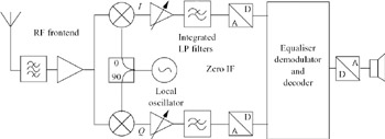
Figure 2.2: Zero-IF receiver
The zero-IF receiver does suffer from some serious limitations. These are mainly associated with unwanted DC offsets and second-order intermodulation products generated in the mixers which occupy the same frequency band as the wanted signal. They can seriously desensitise the receiver and are particularly troublesome in narrowband systems. Nevertheless, some handset manufacturers and silicon suppliers have developed successful zero-IF products for GSM.
By contrast, the zero-IF receiver is ideally suited to wideband systems, such as UMTS. This is because the use of spread-spectrum techniques makes it easier to filter out the DC offsets and some of the second-order intermodulation products without having a significant impact on receiver sensitivity.
2.2.3 Low-IF architecture
At first glance, the low-IF receiver [2, 3], illustrated in Figure 2.3, looks similar to a zero-IF receiver. The crucial difference, however, is that the LO, rather than being positioned at the centre of the wanted signal, is offset by half the channel spacing. In the context of GSM, this increases the IF from zero to 100 kHz. The main justification for this is to separate the wanted signal from the unwanted DC offsets and second-order intermodulation products. This allows the DC offsets to be managed by simple AC coupling without causing serious damage to the wanted signal. A significant proportion of the other second-order products is rejected by the channel filter. As will be described later, the effect can be to permit a substantial reduction in the second-order intercept point (IP2) requirement of the receiver. Alternatively, a low-IF receiver using the same mixers will be considerably more robust than a zero IF receiver when operating in a hostile interference environment. This improvement comes about primarily as a result of the wanted signal having been separated from the second-order intermodulation products, rather than any filtering introduced by the DC breaks.
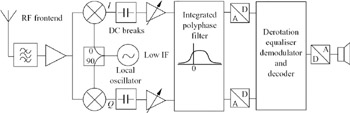
Figure 2.3: Low-IF architecture
In an analogue implementation, the channel filtering is most conveniently realised by means of an active polyphase filter [4], as this provides the greatest immunity to the effect of random spreads in component values. Any consequent lack of image rejection due to imbalances in I and Q only affects one of the adjacent channels, where the selectivity requirements are generally not severe. Such a filter inevitably consumes more power than the two low-pass filters that would be required in a corresponding zero-IF receiver, but the overhead is generally modest. In the context of GSM, it is generally necessary to shift the IF back to zero, after the channel filter, and this derotation process, as shown in Figure 2.3, is best carried out in the digital domain.
|
EAN: 2147483647
Pages: 100