PCI: New Bus on the Block
| |
The PCI bus may have arrived just in time to carry the load that faster networks and multimedia put on the I/O subsystem.
As computer CPUs and memory subsystems advance in performance, the I/O subsystems are challenged to keep up. Video graphics controllers, network adapters, and hard disk controllers demand high levels of data throughput.
The Peripheral Component Interconnect (PCI) bus was developed to address these needs for higher I/O transfer rates. Like EISA, PCI is a 32-bit-wide bus, allowing data to be transferred four bytes at a time. But, while EISA has an 8.33MHz bus clock rate, the PCI 2.0 specification allows for a clock rate of up to 33MHz. The product of the four-byte bus width and 33MHz clock frequency gives PCI a 132Mbyte/sec theoretical maximum throughput, compared to EISA's 33Mbytes/sec.
Although PCI was largely developed by Intel, a company known for its 80x86 family of microprocessors, it was conceived as a processor-independent I/O bus. As an example of this processor independence, Apple Computer's newest PowerPC-based Macintoshes use the PCI bus.
Loading Up
If you've shopped around for PCI-based systems, you've probably noticed that most of today's offerings have three or fewer PCI slots. This is problematic if you are planning to use a PCI-based system as a network file server; servers need lots of slots to handle multiple NICs and disk controllers.
According to Robert McNair, applications engineering manager for Intel's PCI components division (Santa Clara, CA), part of the reason for the relatively low PCI slot-count on today's machines is a bus-loading limitation. A second reason involves the large installed base of ISA and EISA adapter cards, which users will no doubt be reluctant to replace immediately. A system that also contains several EISA or ISA slots-in addition to PCI-can take advantage of this installed base.
As for the bus-loading issue, no matter what device is "driving" the bus ( putting electrical signals onto the bus), it will only be capable of driving a limited number of devices. If there are too many electrical loads, signal voltages may not quite meet their required tolerances, resulting in signal errors. In extreme cases, circuits may be damaged if they are supplied with more current than they can handle.
PCI can drive a maximum of 10 loads, says McNair. In determining bus loading, the PCI chipset that drives the PCI bus itself counts as one load. Any PCI components (such as an embedded PCI graphics or SCSI controller, mounted on the motherboard) count as one load each.
PCI slots are counted as one and one-half to two loads each. Why not one load? If each slot could support only one load, it would create quite a hardship for the designers of PCI add-in boards . This is because you could only have a single PCI device on each card. By allowing cards to present a load equivalent to two PCI loads, the designers of the PCI specification gave board designers more freedom in the types of products they can design.
What these bus-loading rules mean is that a PCI bus will, in most cases, be limited to a maximum of four slots. (As an example, if the PCI chipset is taking one load and a PCI-based graphics controller is taking another, a system designer would have eight loads left to apportion among the slots, which equates to four slots).
System designers can get past the limitations outlined above by using PCI "bridges"-integrated circuits that serve as signal amplifiers and repeaters. Through the use of a bridge, a system designer can hang a second PCI bus off of another one. (But bear in mind that the PCI bridge itself presents a load to the primary bus; it usually counts as one load.)
Other types of bridges may connect either an EISA bus or an ISA bus to a PCI bus. The manner in which bridges are employed can have a significant impact on overall system performance. For example, consider Figure 1, which illustrates two different ways in which to bridge several buses together. In this figure, Approach A represents a cascaded configuration, in which PCI bus 2 is connected (via a PCI-to-PCI bridge) to PCI bus 1. The EISA bus, too, is cascaded from PCI bus 1. Because of this cascaded arrangement, all data flowing to or from any adapters plugged in to any of the PCI or EISA slots must cross PCI bus 1-putting an upper limit of 132Mbytes/sec on total I/O.
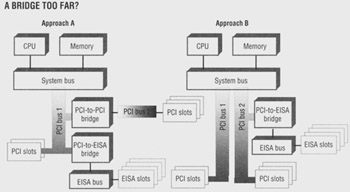
Figure 1: Bridges can be used to connect one PCI bus to another. Other bridges can link a PCI bus to an EISA or ISA bus. But how systems designers use these bridges can impact overall performance. In this example, Approach B offers higher total I/O throughout than Approach A, due to the peer-level arrangement of the two PCI buses in Approach B.
Approach B in Figure 1 shows a second arrangement, which I'll refer to as a peer arrangement because both PCI bus 1 and PCI bus 2 are bridged directly off the system bus. Neither one depends on the other to get or send data. In this case, total system I/O can go as high as 264Mbytes/sec-twice that of Approach A.
Figure 1 doesn't represent any specific computer system. Rather, it illustrates, in a general way, the difference between cascaded and peer-level PCI bus arrangements. Hewlett-Packard (HP, Palo Alto, CA) has begun using these two approaches in the company's NetServer line of network servers. Larry Shintaku, advanced development manager for HP's NetServer division (Santa Clara, CA), says that the company's entry-level NetServers use the cascaded-bus configuration (similar to Approach A, Figure 1)-as do most of the other PCI-based servers from other vendors . HP's high-end NetServers use the peer arrangement, for higher total I/O throughput capability.
On the PCI slot-count issue, Shintaku takes much the same perspective as Intel's McNair, saying that bus-loading constraints are one reason that most of today's PCI systems have relatively few PCI slots, but that there's also a need to have enough ISA (or EISA) slots to accommodate older boards.
In terms of mechanical arrangements, PCI uses a multiplexed data and address bus. This means that the same electrical conductor paths are used to carry data and addresses. (It doesn't carry them both at the same time, however; it alternates as necessary, with one signal line indicating whether the information currently on the bus represents data or an address.)
By multiplexing the data and address information onto one set of conductors, PCI's designers managed to get a fairly low pin-count, with respect to EISA or other 32-bit buses. This reduces cost by allowing a smaller physical connector and takes up less "real estate" on motherboards.
You're In My Slot
PCI's specifiers also came up with a clever way to conserve back-panel space on computers. Because PCI won't replace ISA or EISA overnight, most systems will carry two types of I/O slots, usually a mixture of PCI and EISA or PCI and ISA. There may not be enough physical slots on the back panel to accommodate as many I/O boards as a customer may want (network server applications, in particular, often demand lots of slots), therefore, PCI's designers came up with the concept of "shared" slots. A shared slot, for example, may (depending on its design) be used for either a PCI board/EISA board or a PCI board/ISA board.
Figure 2 shows the layout of a typical shared slot. It is a top view, looking down on the motherboard. EISA cards have their printed circuit boards on one side of the metal mounting bracket that is used to secure the board to the computer's back panel. With PCI, the circuit board is mounted on the other side of the bracket . Looking at the diagram, you can see that this allows two connectors (PCI and EISA, in this example) to be placed side-by-side in the space occupied by one physical slot.
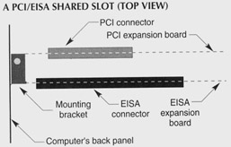
Figure 2: System designers can create "shared" I/O slots, which can be used for either of two types of expansion boards. The shared slot illustrated here will accept either a PCI or EISA card.
Shared slots don't increase the total number of slots-a five-slot system, for example, is still a five-slot system-but by sharing slots, a designer could come up with a system that has three PCI slots and three ISA slots. One of the slots would have to be a shared slot. This arrangement gives users the flexibility to use a combination of three PCI boards and two ISA, or two PCI boards and three ISA.
Intel's McNair notes that PCI's interrupt scheme is different from ISA's. PCI permits several devices to share a single interrupt, provided that all of the devices are capable of sharing interrupts. With the ISA bus, only one device is allowed to use a particular interrupt.
PCI can allow shared interrupts because it uses "level-triggered" interrupts, while the ISA bus uses "edge-triggered" interrupts (EISA can use either). "Level-triggered" means that the computer is sensitive to the voltage level that is on each interrupt line. For example, an interrupt line may be at a 5-volt level when there are no interrupts. When an interrupt occurs, it is signaled by the interrupt line going to 0 volts . (The voltages may vary or the logic inverted from this example, depending on your computer's design; the principle still holds true, however.)
With edge-triggered interrupts, the computer only responds to the transition between one state and the next . In other words, it only pays attention to the leading edge of the voltage waveform on the interrupt line.
When a PCI-based system receives an interrupt on one of the PCI interrupt lines (there are four of them), it knows that one-and possibly more-of the devices using that interrupt line needs attention. It then begins polling each device in turn , to find out which one sent the interrupt. Once the correct device is located, the system will immediately jump to the interrupt handler (also known as an interrupt service routine, or ISR) for that device.
When the ISR is complete, the system returns to the activity it was performing prior to the interruption. But, if the interrupt line previously mentioned is still indicating an interrupt (if the interrupt line is still being held low, in our example), the system will once again poll devices to find out which one is calling for an interrupt, then service that interrupt.
By using a combination of interrupt-driven and polling techniques, PCI can be much more flexible in its interrupt scheme than ISA. Although ISA supports more individual interrupts, the fact that each device must have its own interrupt line means you're more likely to run out of interrupts with ISA.
PCI's ability to have multiple devices sharing a single interrupt line is made possible by its use of level-triggered interrupts. If interrupts were edge-triggered, it is possible that some of the incoming interrupts might be lost. For example, if a second interrupt were to come in while the processor was still in the midst of processing a previous one, the processor would return from servicing the first interrupt but not be aware that a second interrupt had been asserted. With level-triggered interrupts, by contrast, any device assigned to that interrupt line can bring the line low to assert an interrupt. This line will continue to stay low until all pending interrupts have been serviced, ensuring that the processor doesn't miss any incoming interrupts.
PCI should offer enough I/O throughput to satisfy most of today's needs- especially if a dual, peer-level PCI arrangement is used. But PCI's developers have already made plans for expansion, by supporting a future 64-bit bus, and clock rates up to 66MHz. The compact pinout of PCI's multiplexed bus allows a second connector to be placed right behind the first, without taking up too much real estate on the motherboard. McNair says the 66MHz bus may not be needed for a long time-at least on PC-class machines. While high- powered engineering workstations may be able to take advantage of it, bottlenecks in other parts of PC systems may mean they can't effectively make use of the doubled clock rate.
This tutorial, number 87, written by Alan Frank, was originally published in the November 1995 issue of LAN Magazine/Network Magazine.
| |
EAN: 2147483647
Pages: 193