VRF-Aware Feature
| As identified in Chapter 6, "Remote Access and IPSec/MPLS VPN Integration," the trend is toward discretely defining VRF-aware capabilities as part of a managed central services strategy. Some of the traditional services supported by an enterprise network include redundancy, security, and IP addressing. Simple Network Management Protocol (SNMP) is also VRF-aware to allow "virtual" access to the management and Management Information Base (MIB) information. Currently, Cisco supports VRF-aware SNMP infrastructure with which any MIB can be easily made VRF-aware. It is critical that these services are supported in the MPLS-based NGN. If an enterprise customer subscribes to services from an MPLS service provider (SP), co-host services with an SP, or manages his own MPLS network, it is imperative for the enterprise networks to support the existing IP services and management capabilities seamlessly over the new infrastructure. To facilitate this, some of the services are made MPLS-aware, so a single resource can be used to serve multiple VPNs instead of dedicating a resource to a VPN. This reduces equipment investment and operational costs. Several services are made VRF-aware and the portfolio is growing. Each of these applications is made VRF-aware by providing a VRF context for IP lookup within the box. For example, each VRF table is stored separately internal to the box. For any application, the router by default does a lookup in the global table for an IP route, especially if the packets are sourced to and from the router itself. One example is Telnet running on the box and an operator initiates the Telnet session either to the box or from the box to a VPN destination. Then, if Telnet is VRF-aware, the router tries to look up the IP address in the default table (global table). If the application is VRF-aware on the router, then by simply providing the VRF context, the lookup happens in the specific VRF table for packet transmission to the right destination. Note that services enabled on the PE for shared operation need only to be VRF-aware. All other service within the VPN can operate transparently as long as the PE is not part of those services. In other words, if the Telnet session is between two host nodes inside the VPN and not to or from the PE router itself, there is no need for the PE Telnet service to be VRF-aware. Telnet packets that go from and to destinations inside a VPN pass through transparently via the PE. VPN-ID as defined in RFC 2685 is used to uniquely identify VPNs across single or multiple ASes. When using shared services across ASes, VPN-ID can be used on the PE to uniquely identify a VPN for appropriate VRF lookup of traffic. Following is the list of applications and capabilities that are VRF-aware; it is by no means a comprehensive one:
VRF-specific capability helps provide a highly efficient, managed central services capability because, without this, each service needs to be replicated per VPN, as shown in Figure 13-1. Figure 13-1. MPLS/VPN: Before Managed Shared Services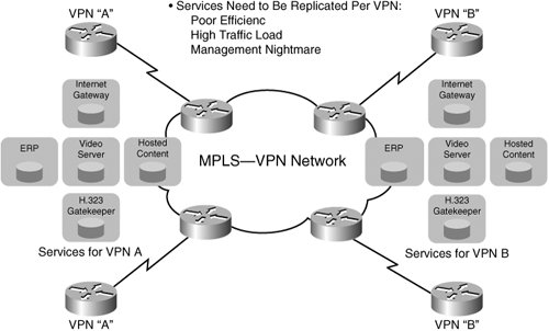 We provide design examples for the following services: DHCP and NAT. IP Addressing: VRF-Aware DHCPIP address assignment and management has been one of the key services required for enterprise networks. Enterprise networks need to support these services in an MPLS VPN environment whether MPLS VPNs are deployed locally or the enterprise customer is subscribing to MPLS VPN services from a service provider. The DHCP server needs to be able to distinguish the requests coming from hosts located in various VPNs so that the replies can be sent to the intended host in a VPN. VPN awareness is added to the DHCP applications in Cisco solutions that address the unique needs in MPLS VPN environments. Several techniques are available that can be used to assign IP addresses. These are:
DHCP can be deployed in various configurations, such as the following:
For all four scenarios, a DHCP server can be located in a global table, in a VRF, or in a common VRF. If MPLS VPNs are deployed in an enterprise network and all the services are being managed within this network, having a centralized DHCP server that services hosts within a company's VPNs makes the most sense. This model helps reduce server replications throughout the network, reducing capital and operational expenses and facilitating ease of provisioning, management, and troubleshooting, as well as preserving IP address space. The supported VPN topologies are hub and spoke, fully meshed sites, and a hybrid model. DHCP Deployment ExamplesThe following examples are DHCP deployment scenarios:
For cases 2 and 3, Spoke-PE1 is the relay agent. It forwards DHCP requests to the designated DHCP server that is associated with a VRF and replies with an assigned IP address back to the hosts. This is an example of using the router as a DHCP server in an IPV4 environment. Remember that VPNs originate on PE unless Multi-VRF is enabled on the CE. Case 6 is an example of supporting sites such as Spoke-Site2 and Hub-Site clients. For this type of connection, use VRF-aware On Demand Address Pool (ODAP) supported with Cisco Network Registrar (CNR5.5 and above). ODAP pool manager downloads pools of IP addresses on appropriate PEs (Hub-PE, Spoke-PE2). The pool can expand or shrink based on address demand. ODAP works with DHCP clients and for devices connected to the PE router using Point-to-Point Protocol (PPP). A PPP session that belongs to a specific VPN is allocated an address only from the ODAP associated with that VPN. These PPP sessions are terminated on a Virtual Home Gateway (VHG)/PE router where the ODAP is configured. The VHG/PE router maps the remote user to the corresponding MPLS VPNs. Case 7 is an example of having DataCenter-PE act as a DHCP server for any clients. This scenario is not supported yet. Support will be implemented based on demand. An IP helper address is needed in any case to get the router to forward BOOTP requests. Configure the IP helper address with the VPN option on the PE interface that connects to the clients. If you have any security concernsfor example, internal or external non-VP clients reaching the DHCP serveryou can put the (PE) interface that is connected to the servers in a VRF. You should use additional IP Security (IPSec) techniques to prevent attacks. Notice that the router sends its own interface IP address as a DHCP server address. So, the DHCP server address should not be known to the clients. Figure 13-2 shows a DHCP relay for MPLS-VPNs serving a single VPN, and Figure 13-3 depicts DHCP relays for shared MPLS-VPNs. Figure 13-2. DHCP Relay for MPLS VPNs Serving: Single VPN Figure 13-3. HCP Relay for MPLS VPNs: Shared Deployment Guideline SummaryThe following list summarizes guidelines for deployment:
VRF-Aware Network Address TranslationFor VPNs that use private address space, you need to do address translation for the hosts that need access to the public domain or a shared services segment. It is common for different VPNs to use overlapping private address space. Thus, you must do address translation before the traffic can access the public domain or shared services located in a shared datacenter. If the enterprise subscribes to VPN services from a service provider and uses private address space, you need to do address translation at the CPE. VRF-aware address translation allows the enterprise customers to offload it to their service provider. Enterprise customers who have deployed MPLS VPNs and use private addresses have options to do address translation at various points within the network. This is a generic hub-and-spoke topology. You can dedicate a NAT PE, multiple NAT PEs, or perform address translation in a distributed manner. For example, you can do address translation at
If the address translation is done at the CE1 devices, you do not need VRF-aware NAT. You can do VRF-aware address translation at the points showing odd numbers in this topology. Note, though, that these are ingress interfaces on PE devices for the traffic coming from remote sites. The advantage is that the address translation load is distributed on multiple PEs. In this type of deployment, you need to keep track of the public IP address range used on each PE. Another approach is to deploy a VRF-aware NAT at interfaces labeled with even numbers in the topology. Similar principles apply for a fully meshed VPN topology. A single IP address pool can be used to assign addresses to multiple VPNs. The IP address pool can also be dedicated to a VPN. If you have a large number of VPNs, provisioning could get cumbersome with increased numbers of access lists and pool statements. On the other hand, it is easier to manage and troubleshoot if you use dedicated IP address pools. Be aware that VRF-aware NAT inherits all the limitations from generic NAT. It supports all the applications supported by generic NAT. In addition, it works the same way as generic NAT. The following section summarizes VRF-aware NAT operation. |
EAN: 2147483647
Pages: 162