Floppy Disk Drives and Media Floppy drives are used primarily for backups of small amounts of data and for the creation of bootable emergency disks with some versions of Windows. Systems built from the early 1990s to the present use one of two types of 3.5-inch drives: -
1.44MB floppy These drives use 3.5-inch double-sided high-density ( DSHD ) media. This type is used by almost all vendors , and supports the 720KB 3.5-inch double-sided double-density ( DSDD ) media used by 3.5-inch drives produced in the 1980s. -
2.88MB floppy These drives use 3.5-inch double-sided extra-density ( DSED ) media. This type was used primarily by IBM. Very little DSED media is available, but these drives can also be used with 1.44MB and 720KB media.  | The 1.44MB 3.5-inch floppy drive in particular has completely replaced the older 5.25-inch drives once used in desktop computers. However, you might encounter a few of these drives retained for access to archival data. The 1.2MB floppy drive can read and write both 1.2MB DSHD and 360KB DSDD media. |
Figure 14.1 shows the data and power connectors used by 3.5-inch floppy drives. Figure 14.1. A typical 3.5-inch drive before (left) and after (right) data and power cables are attached. 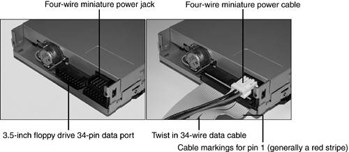 Distinguishing Marks of Different Disk Types The reliability of data stored on a floppy disk can be affected by many factors, including the disks themselves . Figure 14.2 compares 1.44MB and 2.88MB floppy disks. Figure 14.2. A 3.5-inch 720KB floppy disk (left) compared to a 1.44MB floppy disk (right), and a 2.88MB floppy disk (center). 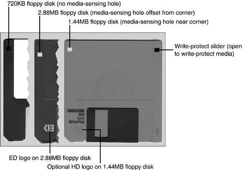 Table 14.1 will help you distinguish between different disk types in use today. Table 14.1. Physical Characteristics of 3.5-Inch Floppy Media | Disk Type | Capacity | Jacket | Reinforced Hub | Write-Protect | Media Sensor | | 3.5-inch DSDD | 720KB | Rigid with metal shutter | N/A | Open write-protect slider | N/A | | 3.5-inch DSHD | 1.44MB | Rigid with metal shutter | N/A | Open write-protect slider | Opposite write-protect slider | | 3.5-inch DSED | 2.88MB | Rigid with metal shutter | N/A | Open write-protect slider | Offset from write-protect slider | Of the disks pictured in Figure 14.2, only the 3.5-inch DSHD disk is commonly used today. 1.44MB disks are often marked HD on their front and always have a media-sensing hole in the opposite corner from the write-enable/protect slider. | | Some desktop and portable systems might use an LS-120 or LS-240 SuperDisk drive in place of a standard 1.44MB floppy drive. These drives not only can read and write 1.44MB and 720KB 3.5-inch floppy media, but can also use high-capacity 3.5-inch media. The LS-120 SuperDisk uses 120MB media, and the LS-240 SuperDisk can use 120MB or 240MB media. These drives usually plug into the ATA/IDE interface if internal, or the parallel or USB port if external. |
BIOS Settings Required for Floppy Disk Drive Support All 286-based and higher systems built since the late 1980s can support all but 2.88MB floppy drives through ROM BIOS configuration and the use of MS-DOS 3.3 or higher. Systems require specific BIOS support to use 2.88MB drives as well as a high-speed floppy controller on the motherboard or add-on card. Floppy Disk Drive Hardware Configuration Floppy disk drive hardware configuration depends on several factors, including -
Correct CMOS configuration The system's BIOS configuration screen must have the correct drive selected for A: and B:. -
Correct cable positioning and attachment The position of the drive(s) on the cable determine which is A: and which is B:. If the cable is not oriented properly, the drive will spin continuously. The standard floppy disk drive interface uses a single IRQ and single I/O port address range, whether the interface is built in or on an expansion card: The standard floppy disk drive interface can support two drives: drive A: and drive B:. However, some recent systems support only one floppy drive (A:). Although the first 5.25-inch floppy drives used jumpers to determine A: and B: assignments, more recent 5.25-inch and all 3.5-inch floppy drives rely on the data cable. The 34-pin floppy disk drive data cable has wires numbered 10 to 16 twisted in reverse between the connectors for drive A: and drive B: (refer to Figure 14.3). The drive beyond the twist is automatically designated as drive A:; the drive connected between the twisted and the untwisted end of the cable (which connects to the floppy controller) is automatically designated as drive B:. Figure 14.3. Two types of floppy drive cables compared. On the left, a cable designed for 3.5-inch drives only; on the right, a cable designed for 3.5-inch and 5.25-inch drives.  Figure 14.3 compares five-connector universal (3.5-inch/5.25-inch) and three-connector 3.5-inch floppy cables. (The cable connector to the floppy controller is not visible in this photo.) Floppy Disk Drive Physical Installation and Removal To install a 3.5-inch 1.44MB floppy disk drive as drive A:, follow these steps: -
Select an empty 3.5-inch external drive bay; an external drive bay is a drive bay with a corresponding opening in the case. -
Remove the dummy face plate from the case front. -
For a tower system, remove the left side panel (as seen from the front). For a desktop system, remove the top. -
If the 3.5-inch drive bay is a removable "cage," remove it from the system. This might involve pushing on a spring-loaded tab, as in Figure 14.4 or removing a screw. Some drive bays pull straight out (as here), whereas others swing to one side. Figure 14.4. A typical cage used by many tower cases for 3.5-inch drives.  -
Remove the floppy disk drive from its protective packaging. Test the screws you intend to use to secure the drive and ensure they're properly threaded and the correct length. -
Check the bottom or rear panel of the drive for markings indicating pin 1; if no markings are found, assume pin 1 is the pin closest to the power supply connector. -
Attach the 34-pin connector at the end of the floppy disk drive data cable with the twist to the data connector on the drive. -
Run the other end of the floppy disk drive data cable through the drive bay into the interior of the computer. Then, connect it to the floppy disk drive interface on the motherboard or add-on card. -
Attach the correct type of four-wire power cable to the drive. You might need to slide the drive partway into the drive bay to make the connection. -
Secure the drive to the drive bay with the screws supplied with the drive or with the computer. -
Replace the drive bay into the computer if present (see Figure 14.5). Figure 14.5. A removable drive cage with the attachment screws for the floppy disk drive and hard drive. The opposite corner of each drive is also secured with screws (not shown).  -
Double check power and data cable keying before starting the computer. -
Follow these steps in reverse to remove the drive from the system. BIOS Configuration Floppy disk drives cannot be detected by the system; you must manually configure the floppy disk drive or floppy disk drives you add to the system. To configure the floppy disk drive in the ROM BIOS, follow these steps: -
Verify the correct physical installation as listed previously. -
Turn on the monitor and the computer. -
Press the appropriate key(s) to start the BIOS configuration program. -
Open the standard configuration menu. -
Select Drive A: or the first floppy disk drive. -
Use the appropriate keys to scroll through the choices; 3.5-inch 1.44MB is the correct choice for most recent and current systems (see Figure 14.6). Figure 14.6. Viewing floppy drive type options in the BIOS setup program of a typical system.  -
No other changes are necessary, so save your changes and exit to reboot the system. The Care of Floppy Disks, Data, and Drives You can protect the data on your floppy disks by following these recommendations; most of these suggestions also apply to higher-capacity removable media such as Zip, Jaz, LS-120, and tape backups: -
Do not open the protective metal shutter on 3.5-inch disks. -
Store disks away from sources of magnetism (CRT monitors and magnetized tools) or heat. -
Open the sliding write-protect cover on 3.5-inch disks to prevent the contents of the disk from being changed. Floppy disk drives are a type of magnetic storage in which the read/write heads make direct contact with the media. This is similar to the way that tape drives work, and just like tape backup, music cassette, or VCR heads, a floppy disk drive's read/write heads can become contaminated by dust, dirt, smoke, or magnetic particles flaking off the disk's media surfaces. For this reason, periodic maintenance of floppy disk drives will help to avoid the need to troubleshoot drives that cannot reliably read or write data. | | 5.25-inch media should be kept in protective paper or cardboard sleeves. To prevent 5.25-inch disks from being erased or altered , cover the write-protect notch on the right side of the disk with opaque tape. |
The following are some guidelines for cleaning a floppy disk drive: -
Approximately every six months, or more often in dirty or smoke-filled conditions, use a wet-type head-cleaning disk on the drive. These cleaning kits use a special cleaning floppy disk that contains cleaning media in place of magnetic media, along with an alcohol-based cleaner. Add a few drops to the media inside the cleaning disk, slide it into the drive, and activate the drive with a command such as DIR or by using the Windows Explorer to clean the heads. Allow the heads to dry for about 30 minutes before using the drive. -
Whenever you open a system for any type of maintenance or checkup, review the condition of the floppy disk drive(s). Use compressed air to remove fuzz or hair from the drive heads and check the mechanism for smooth operation. |