IDEATA Hard Disks
| < Day Day Up > |
IDE/ATA Hard DisksIntegrated Drive Electronics ( IDE ) began to replace the older drive interfaces starting in the late 1980s and continues to be, by far, the most popular drive interface used today. IDE drives were originally used in systems designed for ST-412/506 hard drives , and some of their characteristics date back to the need to be compatible with old BIOSs. tip
IDE was originally designed for hard drives, but several other types of storage devices can also be attached to it:
tip
These types of drives are referred to as AT Attachment Packet Interface ( ATAPI ) drives, and they use the same master / slave / cable select jumpers and 40-pin data cable as standard IDE drives do. The system BIOS on recent systems supports minimal functions for these drives, but software drivers are used to provide most functions. These devices should be installed on the secondary IDE channel, and hard drives should be installed on the primary IDE channel. IDE/ATA Hardware ResourcesThe IDE/ATA hard disk interface, whether found on the motherboard or as an add-on card, uses the following resources. These resources are listed in Table 14.2. Table 14.2. Standard Hardware Resource Use for IDE/ATA Hard Drive Interfaces
Each IDE hard drive interface, also known as an IDE channel , can operate two IDE drives. Therefore, systems with two IDE interfaces can operate up to four IDE drives. EIDE and ATA StandardsBecause the original IDE drives were developed as proprietary drive interfaces for use with brands such as Compaq and Zenith, the first IDE drives had major problems with compatibility and could not be autoconfigured by the BIOS. Although it can still be difficult to "mix and match" some IDE drives from different vendors, a series of standards for IDE drives are referred to as the ATA specifications (AT Attachment). Table 14.3 provides an overview of the differences in the various ATA/IDE specifications. Table 14.3. ATA/IDE Specifications and Features
An ATA-7 standard is currently in draft form. It is expected to provide standards for external hard drives and for the Ultra ATA-133 transfer rate (FastDrive; 133MBps) developed by Maxtor and available in current Maxtor drives. Enhanced IDE is a marketing term used by some vendors to refer to the enhancements listed as ATA-2 in Table 14.3. Serial ATASerial ATA ( SATA ) is a development of the ATA/IDE standard that provides a pathway to faster drives, greater reliability, and simpler installation than ATA/IDE.
Serial ATA uses a single seven-wire data cable, which uses high-speed serial technology instead of the parallel technology used by ATA/IDE to transmit signals between the drive and host adapter. Unlike ATA/IDE drives, SATA drives use a direct one-to-one connection between the drive and the host adapter. Thus, no jumpers are necessary to configure the drive. Hooray! Serial ATA uses the same commands as ATA/IDE, so SATA drives and host adapters can be retrofitted to existing systems. SATA drives can be prepared by Windows 98 and more recent versions. Some recent systems include one or more SATA host adapters on the motherboard. On such systems, after the SATA host adapter is enabled in the system BIOS, SATA drives are configured just as ATA/IDE drives are. The original version of SATA, SATA-150, has a maximum data transfer rate of 150MBps. Faster versions are expected in the future. ATA RAID TypesRAID (redundant array of inexpensive drives) is a method for creating a faster or safer single logical hard disk drive from two or more identical physical drives. RAID arrays have been common for years on servers using SCSI-interface drives. However, a number of recent systems feature ATA RAID or SATA RAID host adapters on the motherboard. ATA and SATA RAID host adapter cards can also be retrofitted to systems lacking onboard RAID support. ATA and SATA RAID types include the following:
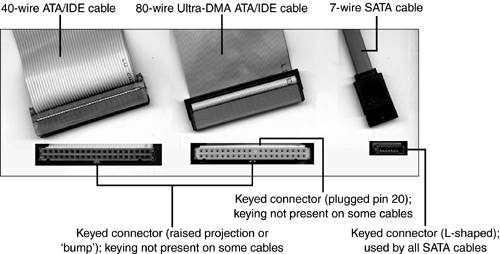
Most motherboards support only RAID 0 and RAID 1. Some host adapters support RAID 0, 1, and 0+1. ATA or SATA RAID host adapters can sometimes be configured to work as normal ATA or SATA host adapters. Check the system BIOS setup or add-on card host adapter setup for details. ATA and Serial ATA CablingATA/IDE drives use one of two types of cables, depending upon their speed, whereas Serial ATA drives use one type of cable:
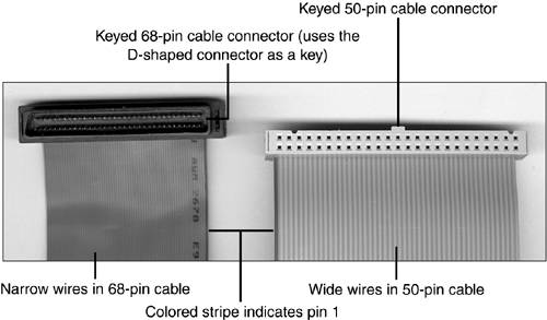
Figure 14.7 compares these cables to each other. Note the ridged appearance of the 40-wire ATA/IDE cable compared to the smoother 80-wire cable; the 40-wire cable uses thicker wires. Figure 14.7. 40-wire and 80-wire ATA/IDE cables compared to an SATA cable.
IDE Data Cable Keying StandardsDepending upon the design of the ATA/IDE cable and connectors used in a particular system, you might discover difficulties in properly connecting devices:
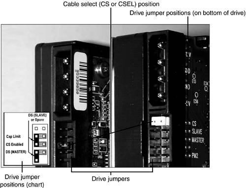
Drive Jumpers and Cable SelectWith two drives possible per ATA/IDE cable, the ATA/IDE interface uses one of two methods to determine which drive is master and which is slave:
Four different jumper positions are available on the bottom or rear of a typical IDE hard drive:
Figure 14.8 shows two ATA/IDE hard drives configured for cable select. The Cap Limit jumper shown in Figure 14.8 is used only on systems that cannot use the drive at full capacity.
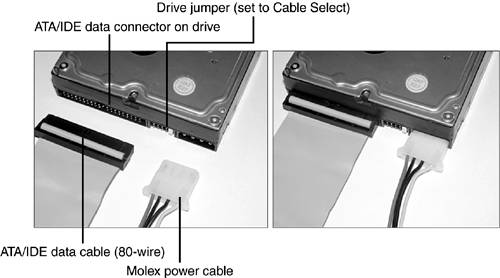
ATA/IDE Hard Drive Physical InstallationThe following steps apply to typical ATA/IDE drive installations. If you are installing an ATAPI drive, you might use a 5.25-inch bay, but the other steps will be the same.
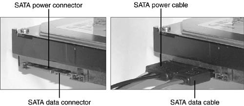
Figure 14.10 shows a typical ATA/IDE drive before and after power and data cables are attached. Figure 14.10. Attaching power and data cables to a typical ATA/IDE drive. SATA Hard Drive Physical InstallationThe process of installing an SATA drive differs from that used for installing an ATA/IDE drive because there are no master or slave jumpers and the SATA data cable goes directly from host adapter to drive. The following instructions assume the system already has an onboard or add-on card SATA host adapter already installed. If you need to install an SATA host adapter, see the next section for details.
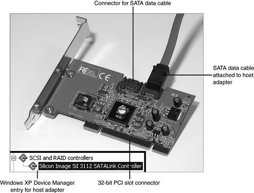
Figure 14.11 shows a typical SATA drive. Figure 14.12 shows typical ATA/IDE and SATA host adapter connections on a recent motherboard. Figure 14.11. Attaching power and data cables to a typical SATA drive. Figure 14.12. ATA/IDE and SATA host adapters on a recent motherboard. Installing an SATA Host AdapterMost systems don't include an SATA host adapter on the motherboard. Thus, to add an SATA drive to many systems, you will also need to install an SATA host adapter card such as the one pictured in Figure 14.13. Follow this procedure:
Figure 14.13. A typical SATA host adapter card that supports two SATA drives. The inset shows how this host adapter appears in the Windows XP Device Manager after installation. BIOS ConfigurationFor ATA/IDE and SATA drives controlled by the motherboard BIOS, the following information must be provided:
Hard drive geometry refers to several factors used to calculate the capacity of a hard drive. These factors include the following:
The surface of any disk-based magnetic media is divided into concentric circles called tracks . Each track contains multiple sectors. A sector contains 512 bytes of data, and is the smallest data storage area used by disk drives.
Each side of a hard disk platter used for data storage has a read-write head that moves across the media. There are many tracks on each hard disk platter, and all the tracks on all the platters are added together to obtain the cylinder count. Figure 14.14 helps you visualize sectors, tracks, and cylinders. Figure 14.14. Tracks, sectors, and cylinders compared. Before the drive can be prepared by the operating system, it must be properly identified by the system BIOS. Depending on the age of the system and the size of the ATA/IDE hard drive, there are two different methods used for configuring an ATA/IDE or SATA drive:
Manual Entry of IDE ParametersThis feature started to become common in the BIOS configuration program around 1990, and virtually all systems still allow this today. Systems with this feature have a user-defined drive type that enables you to manually enter the correct cylinders, heads, sectors per track, and special configuration information. This information is not stored in the BIOS itself, but rather in the CMOS memory, which can be lost due to battery failure or other problems.
Today, this method of defining the hard disk geometry is used primarily when a drive that was prepared using a different disk geometry than that recommended by the manufacturer is being reinstalled in a system or is being moved to another system. Auto-detection of the IDE Hard Drive TypeAuto-detection is a variation on the user-defined drive type. Auto-detection was developed in the early 1990s, enabling the BIOS to query the drive for the correct configuration information. This information also is placed in the user-defined drive type and stored in the CMOS memory (see Figure 14.15). Figure 14.15. Configuring an 80GB Western Digital ATA/IDE drive with the auto-detection feature in a typical recent system BIOS. Auto-detection is the best way to install a new ATA/IDE or SATA drive because other settings such as LBA translation, block mode (multi-sector transfers), and UDMA transfer rates will also be configured properly. Some BIOSs perform the automatic detection of the drive type every time you start the system by default. Although this enables you to skip configuring the hard drive setting, it also takes longer to start the system and prevents the use of nonstandard configurations for compatibility reasons. To save time during the boot process and to allow you to see the actual values used for the drive in the system BIOS, you can use these methods:
Depending on the system, removable-media ATAPI (ARMD) drives such as Zip and LS-120 should be configured as Not Present or Auto in the system BIOS setup or as ARMD drives depending upon the BIOS options listed. These drives do not have geometry values to enter in the system. The CD-ROM setting should be used for ATAPI CD-ROM and similar optical drives, such as CD-R, CD-RW, and DVD. Using the correct BIOS configuration for ATAPI drives will enable them to be used to boot the system on drives and systems that support booting from ATAPI devices. caution
Creating an ATA or SATA RAID ArrayAn ATA or SATA RAID array generally requires
Because RAID arrays use off-the-shelf drives, the only difference in the physical installation of drives in a RAID array is where they are connected. They must be connected to a motherboard or add-on card that has RAID support. After the drive(s) used to create the array are connected to the RAID array's host adapter, restart the computer. Start the system BIOS setup program and enable the RAID host adapter if necessary. Save changes and exit the BIOS setup program. After enabling the RAID array host adapter, follow the vendor instructions to create the array. Generally, this requires you to activate the RAID array setup program when you start the computer and follow the prompts to select the type of array desired. After the RAID array is configured, the drives are handled as a single physical drive by the system. Overcoming Hard Disk Capacity Limitations with LBA ModeWhen the IDE interface was developed, several limitations on the total capacity of an IDE hard disk existed:
These limitations resulted in a total capacity of 504MiB, or approximately 528 million bytes. By 1994, these limitations were no longer theoretical; users were able to purchase drives that exceeded this size and a BIOS-based way was needed to ensure reliable access to the drives' full capacity. Previously, systems that were incapable of using the entire capacity of a drive would use a software driver such as OnTrack's Disk Manager, but this approach could be risky to data if the driver or special drive configuration failed. The most common method for enabling larger IDE hard drives to be used is called Logical Block Addressing ( LBA ) . How does LBA work? LBA mode alters how the drive is accessed internally. It increases the BIOS limit to 255 heads and works around the MS-DOS limitation of 1,024 cylinders per drive by dividing the cylinders and multiplying the heads by the same factor. Thus, an LBA mode drive has the same capacity as a non-LBA mode drive, but its configuration is different. caution
For example, assume an ATA/IDE hard drive has a factory-defined configuration of 13,328 cylinders, 15 heads, and 63 sectors per track. To determine the drive capacity, multiply the cylinders by the heads by the sectors per track. Divide the result by 2,048, and the capacity is 6.15GiB (about 6.4GB). However, if you don't enable LBA mode, only the first 1,024 cylinders are recognized by the system, shrinking the drive to 504MiB (528MB).
Which of the three values listed previously is the problem? The cylinder count! When LBA mode is enabled, the following changes take place in the logical geometry of the drive:
Both of these new logical values fall below the BIOS limits adjusted by LBA. Consequently, the 6.4GB drive is recognized at full capacity. That's a pretty good trick! Remember, every operating system with a Microsoft logofrom dusty old MS-DOS to the latest Windows versionis incapable of using more than 504MiB of any IDE/ATA or SATA hard drive unless LBA mode is enabled (SCSI has the same limitation, but it's handled a different way). It's Not Nice to Fool Around with LBA!If LBA mode is disabled after a drive has been prepared using LBA mode, the drive will not work properly, to put it mildly. caution
With MS-DOS, the system at some point might try to write to data stored on areas past the barrier of 1,024 cylinders that LBA mode overcomes. Without LBA mode to translate the drive's full capacity, the system will loop back to the beginning of the drive and overwrite the partition table and file allocation table, destroying the drive's contents. Ouch! If you're running Windows (all 99.9% of you), don't panic. Windows won't boot if you turn off LBA mode, but you won't lose any data. If you're the paranoid type (did I enable LBA mode?), you can use your operating system's disk preparation software to find out if LBA is working. See Chapter 15 for details. Additional Drive-Size LimitationsEarly versions of LBA-mode BIOS could not handle drives of more than 4,095 cylinders (approximately 2.1GB); many more recent systems cannot handle drives with more than 16,384 cylinders (approximately 8.4GB). Support for drives with more than 16,384 cylinders, referred to as Extended INT13h or EBIOS support, also requires support in the operating system (Windows 95 or later). Whenever possible, you should install a system BIOS upgrade to handle limitations of these types. Check out Chapter 6, "BIOS and CMOS Configuration," for the details. If a BIOS upgrade is not available for your system, you can install an ATA host adapter card with an auxiliary BIOS onboard. The BIOS chip on the card can override your existing BIOS to provide the additional support necessary to operate the hard drive at full capacity. An ATA host adapter card is installed using a process similar to that used to install an SATA host adapter card. Like the SATA card, it uses an empty PCI slot. The upgrade version of Windows 95 and the original OEM version cannot use drives larger than 8.4GB because they use the file system (FAT16) inherited from MS-DOS. The OSR 2.x (Windows 95B/C) versions can use drives up to 32GB in size. Later versions of Windows can use drives over 32GB in size. For more details, see Chapter 15. ATA/IDE Performance OptimizationIf your hard drive is stuck in first gear, so is your system. Fortunately, most systems that support LBA mode also offer several different ways to optimize the performance of IDE drives and devices. These include
caution
PIO and DMA Transfer ModesIDE hard drives are capable of operating at a wide variety of transfer speeds. Depending on when the drive was built, IDE hard drives are designed to run in one of two modes:
These modes refer to different peak transfer rates the hard drive can achieve. Some systems automatically determine the correct transfer rate, whereas others require you to select the correct speed from a list of options. Selecting transfer rates too fast for the drive can cause data corruption, and selecting rates that are too low can slow down the system. To achieve a given transfer rate, the hard disk, the host adapter (card or built-in), and the data cable must be capable of that rate. In addition, the host adapter must be configured to run at that rate. Tables 14.4 and 14.5 list the most common transfer rates. Check the drive documentation or with the drive vendor for the correct rating for a given drive. Table 14.4. PIO Peak Transfer Rates
Although PIO modes 3 and 4 require a fast 32-bit IDE interface, not every VL-Bus card is capable of such transfer rates; some require software drivers to achieve mode 3/mode 4 speeds. Check the documentation for the host adapter card or the BIOS configuration screen for systems using a built-in ATA/IDE interface to find out which speeds are supported. Table 14.5. UDMA (Ultra ATA) Peak Transfer Rates
These modes are backward compatible, enabling you to select the fastest available mode if your system lacks the correct mode for your drive. ATA/IDE drives are backward compatible; you can select a slower UDMA mode than the drive supports if your system doesn't support the correct UDMA mode, or you can use PIO modes if your system has no UDMA options in the BIOS. Performance will be slower, but the drive will still work.
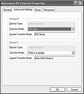
Note that UDMA 4 (UDMA-66) and faster modes require the use of a 40-pin, 80-wire cable previously shown in Figure 14.9. If a 40-wire cable is used, UDMA 2 (UDMA-33) is the fastest speed possible. IDE Block ModeIDE block mode refers to an improved method of data handling. Originally, a hard drive was allowed to read only a single 512-byte sector before the drive sent an IRQ to the CPU. Early in their history, some IDE hard drives began to use a different method called block mode, which enabled the drive to read multiple sectors, or blocks, of data before an IRQ was sent. Virtually all recent drives support block mode. Enable it (also called multisector transfers, as shown in Figure 14.16) in the system BIOS to get the performance expected from the drive. Figure 14.16. The secondary IDE channel on this system is configured to run one drive in PIO mode and one drive in UDMA mode. tip
Most recent systems automatically determine block mode capability when they auto-detect the drive. Others require that you enable or disable block mode manually, and still others enable you to select the number of blocks the drive can read. Some very old ATA/IDE drives do not support block mode and run more slowly when it is enabled. If you must set block mode manually, check with the drive vendor to see whether the drive supports block mode and what options to select if it does. IDE Busmastering DriversA third way to improve IDE hard disk performance is to install busmastering drivers for the IDE host interface. A busmaster bypasses the CPU for data transfers between memory and the hard disk interface. This option is both operating system specific and motherboard/host adapter specific. Only systems running Windows 9x and newer versionsbut not MS-DOS, Windows NT 3.51, or Windows NT 4.0 before Service Pack 3can use busmastering drivers. Most newer systems have motherboards that support busmastering drivers. Check with the motherboard or system vendor for busmastering information. Busmastering drivers require special support from the motherboard's chipset. The original retail versions of Windows 95 and Windows NT 4.0 don't include busmastering drivers (get them from the motherboard or motherboard chipset vendor), but Windows 95 OSR 2.x (also called Windows 95B), Windows 98, and newer versions include busmastering support for motherboards with the correct Intel chipsets. Motherboards using other chipsets might require that you download the correct driver from the motherboard vendor if you are using Windows 95 OSR 2.x; Windows 98 and newer versions include busmastering drivers for major non-Intel chipsets. In most cases, you must manually install the correct driver. If your motherboard includes a driver CD, it might contain more up-to-date busmastering drivers than those included with Windows. Because busmastering bypasses the CPU, be sure you are installing the correct drivers. Carefully read the motherboard or system vendor's instructions. You might not be able to use busmastering drivers if you use a CD-R or CD-RW drive connected to the IDE interface. In such cases, use the regular IDE host adapter driver supplied with Windows. Enabling DMA Transfers for IDE Devices in WindowsAll versions of Windows from Windows NT 4.0 (Service Pack 3 and greater) and Windows 95 up through Windows XP enable the user to allow DMA transfers between ATA/IDE devices and the system. DMA transfers bypass the CPU for faster performance and are particularly useful for optimizing the performance of both hard drives and optical drives, such as high-speed CD-ROM drives and DVD drives.
Follow this procedure to enable DMA transfers for a particular IDE device in Windows 9x/Me:
Repeat this procedure for each IDE device. With Windows 2000/XP, follow this procedure:
If DMA is not available, you might need to install the correct busmastering driver for your system. Adjusting Disk Caching Settings in WindowsDisk caches use a portion of memory to hold information flowing to and from disk drives. The system accesses the cache memory before accessing the main memory. If the information on disk is already in the cache memory, it is accessed far more quickly than if it were read from disk. Disk cache software is incorporated into Windows 9x and newer Windows versions. (MS-DOS and Windows 9x also include the Smartdrv.exe disk cache program for use at a command prompt.) The disk cache in Windows 9x and newer versions automatically adjusts to increases in physical RAMas more RAM is added, the amount of RAM used for disk caching increases. The disk cache also varies in sizethe amount of RAM used for disk caching varies with system activity. Windows uses two types of disk caching:
By default, Windows uses write-behind caching for hard drives and read-only caching for floppy, removable-media, and CD-ROM/optical drives. You can alter Windows 9x and Me's disk-caching settings by following this procedure:
To enable Windows to use disk caching for hard drives most effectively, perform the following steps:
To enable write-behind caching for floppy and other removable disk drives, follow this procedure:
You must make sure all data has been saved to the disk before removing it. To maximize caching for CD-ROM drives, follow this procedure:
You can disable write-behind disk caching by following this procedure (recommended for troubleshooting only because it slows down the system significantly):
To complete the changes, click OK and restart the system when prompted. To adjust disk-cache settings for Windows 2000/XP, follow this procedure:
|
| < Day Day Up > |
EAN: N/A
Pages: 310