Configuring Token Ring Switching on the Catalyst 3920
| < Free Open Study > |
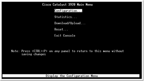
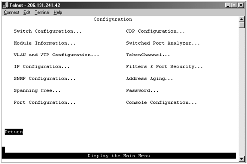
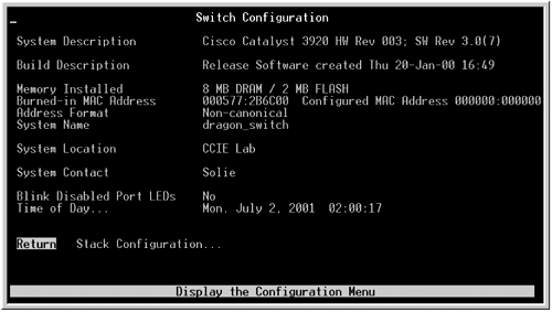
| Many of the same concepts that are found in Ethernet switching apply directly to Token Ring switches. For example, VLANs, VTP domains, and management VLANs are all found on Token Ring switches. For that reason, we will not spend a lot of time redefining these terms and their application. Instead, we will focus primarily on switch configuration. The Catalyst 3920 does not have a standard command-line interface for configuration. Instead, the configuration is totally menu or panel-driven. The cursor keys allow you to select different panel options. To a large extent, this makes the configuration of the switches easy because there is no syntax to remember. Figure 2-22 shows the main panel of the Catalyst 3920 Token Ring switch. Figure 2-22. Initial Configuration Panel The configuration panel is where the TrBRFs, TrCRFs, VLANs, management, and other software features of the switch are configured. The statistics panel is where the show commands for the switch reside. Port status, VTP status, and other important information about the operation of the switch can be viewed . The download/upload panel is where you can upgrade the Catalyst software. Finally, the reset panel is where you can clear NVRAM and reload the switch. Specifically, here is a quick guide to the important setting in each panel. The Switch Configuration PanelFigure 2-23 shows the switch configuration panel. Figure 2-23. Switch Configuration Panel The panels available in the switch configuration panel are as follows :
The Statistics PanelThis panel allows you to display various status information of the ports, VLANs, VTP, and other important information. The information panels that you can view include the following:
The Download/Upload PanelFrom this panel, you can upgrade the switch's IOS. You can upgrade the switch through TFTP or the RS-232 interface. The Reset PanelFrom this panel, you can clear the NVRAM on the switch as well as reset it. The download/upload panel allows you to perform the following:
Configuring VLANs on the Catalyst 3920The logical steps for configuring VLANs for Token Ring resemble the same steps that you use for configuring Ethernet VLANs. With Token Ring, however, you must define rings and bridges, which require a few extra steps. The steps for configuring VLANs on the Catalyst 3920 switch are as follows:
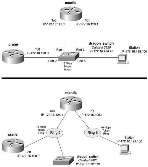
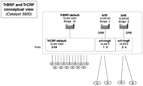
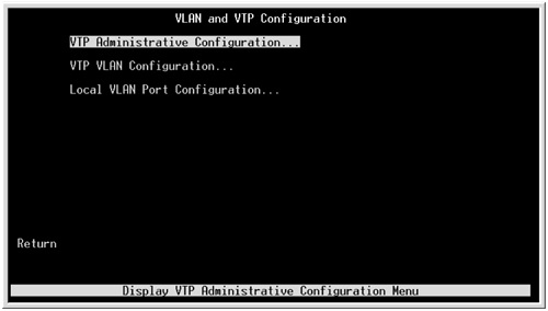
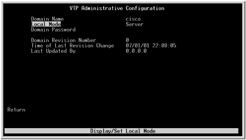
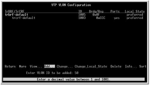
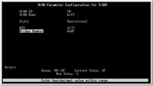
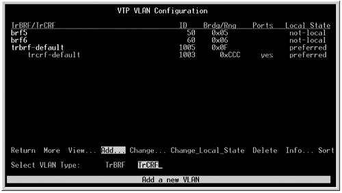
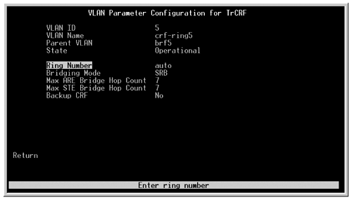
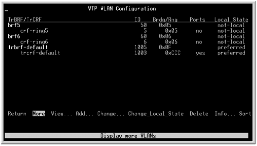
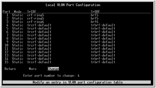
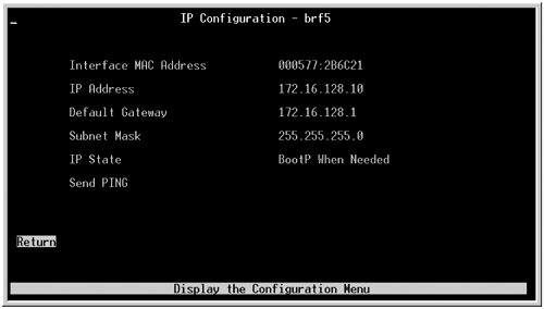
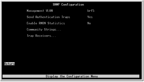
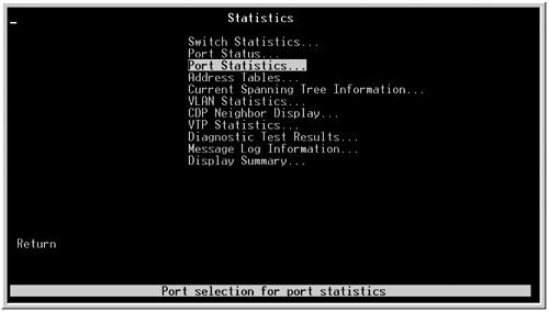
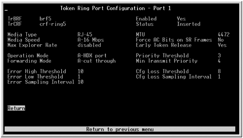
Configuring Token Ring switching involves configuring a TrBRF VLAN and TrCRF VLAN. This relationship can get rather confusing because there are two VLANs, rings, bridges, and so on. For this reason, you should really take the extra time and lay out a small diagram showing the logical relationships among all these entities. Figure 2-24 shows two perspectives of the same Token Ring network. The dragon_switch is Cisco Catalyst 3920; it connects two routers and a user workstation. Let's walk through the six-step process to configure this switched Token Ring network. Figure 2-24. Token Ring Switched Network Model Step 1: Planning TrBRFs, TrCRFs, Ring Numbers, Bridge Numbers, and VLANsIn Step 1, you plan for VLANs, TrBRFs, and TrCRFs. Figure 2-25 diagrams the network from the dragon_switch perspective. You will define two TrBRFs and the associated VLAN and bridge number for them. You also need to define two TrCRFs, the VLAN for them, and an appropriate ring number. The TrCRF is linked to the TrBRF by declaring it a parent. The TrCRF is not linked to the TrBRF by a common VLAN. The VLANs and bridge numbers do not need to match. Figure 2-25. Defining TrBRFs and TrCRFs To help self-document the network, try to form some logical naming convention. In this example, TrBRF is called brf5; it is on VLAN 50 and bridge 5. It is the parent of crf-ring5, which is VLAN 5, which contains ring 5. The other TrBRF will be called brf6 and has VLAN 60 and bridge 6. This TrBRF will be the parent of TrCRF crf-ring6, and crf-ring6 contains VLAN 6 and, you guessed it, ring 6. Step 2: Configuring VTPIn Step 2, you can begin to configure the switch. From the initial configuration panel, select the VLAN and VTP configuration panel. From this panel, you can enter the VTP administrative configuration panel, shown in Figure 2-26. In the VTP administrative configuration panel, you can set the VTP domain name, VTP mode, and a password, if you are configuring one. Figure 2-26. VLAN and VTP Configuration Panel Figure 2-27 displays the VTP administrative configuration panel with the configuration of cisco as the VTP domain name. Figure 2-27. VTP Administrative Configuration Panel Step 3: Configuring TrBRF VLAN(s) and Assigning a Bridge Number to Each TrBRFStep 3 tells you to configure TrBRFs and their associated VLANs and assign a bridge number to the TrBRF. As mentioned previously, you will need to configure two TrBRFs. TrBRFs are configured from selecting the VTP VLAN configuration panel under the same VLAN and VTP configuration panel. From this panel, select Add to create a new TrBRF. Notice that it says to enter a VLAN; this is the VLAN within the TrBRF. Figures 2-28 and 2-29 display the creation of the TrBRF brf5 VLAN 50. Figure 2-28. VTP VLAN Configuration Panel Figure 2-29. VLAN Parameters Configuration Panel When you create a new VLAN, the switch prompts you to make it either a TrBRF or a TrCRF VLAN. By selecting the TrBRF option when you create the VLAN, you are taken to the VLAN Configuration Parameters menu. From this menu, you can enter the TrBRF name and change the VLAN ID, state, and MTU. This menu also allows you to select the bridge number for the VLAN. The bridge number is displayed and entered in hexadecimal format. When performing source-route bridging in the future, be careful not to get bridge IDs mixed up by entering some in hex and some in decimal. Figure 2-29 displays the VLAN parameters configuration panel. Step 4: Configuring TrCRFs VLANs and Assigning a Parent TrBRF and an Optional Ring NumberAfter both TrBRF VLANs have been defined, Step 4 calls for you to define the TrCRFs and link them to a parent TrBRFs. To create a TrCRF, create another unique VLAN in the same manner as mentioned previously. This VLAN is not used to link the TrCRF to the TrBRF, and it needs to have a unique VLAN ID. When prompted for the VLAN type, select TrCRF. Example 2-30 displays the creation of TrCRF VLAN 5. The VTP VLAN Configuration menu for TrCRFs can be found in Figure 2-31. From this panel, you can assign the VLAN a name and parent VLAN. We have named this VLAN crf-ring5 for some extra documentation. Most important is the parent VLAN; here, you want to assign a parent VLAN of brf5. The ring number is set at a default of auto, which means that the switch will be capable of determining from the RIF what the actual ring number is. In this example, you want to statically configure the ring to be ring 5. The ring number is displayed and entered in hexadecimal. Figure 2-30. VTP VLAN Configuration Panel Figure 2-31. VLAN Parameter Configuration Panel Figure 2-32 displays the VTP VLAN configuration panel listing the new VLANs created. Figure 2-32. VTP VLAN Configuration Panel Step 5: Assigning Ports to TrCRFsStep 5 involves configuring the actual Token Ring switch ports and assigning them to a TrCRF VLAN. From the VLAN and VTP configuration panel, the third option, Local VLAN Port Configuration, allows you to change the default TrCRF that all the ports are assigned to. As mentioned previously, all ports are assigned to the TrCRF called TrCRF-default. When you select the Change option, the switch prompts you for the port that you want to change. After the port has been entered, the switch presents you with the current TrCRFs that it is aware of and allows you to change these. Figure 2-33 shows the Local VLAN port configuration panel after ports 1 to 3 have been modified. Figure 2-33. Local VLAN Port Configuration At this point in the configuration, the switch is fully operational. To configure the routers in this network, you simply need to configure the Token Ring interface and basic routing. Example 2-46 illustrates a simple Token Ring configuration, such as the one on the crane router. Example 2-46 Basic Token Ring Configuration on the crane Routercrane(config)# int tokenRing 0 crane(config-if)# ring-speed 16 crane(config-if)# ip address 172.16.128.3 255.255.255.0 crane(config-if)# no shut Step 6: Configuring Switch ManagementThe final step in the configuration is to set up IP access and management. Switch management, such as contact name and information, and canonical address formats can changed from the switch configuration panel. Figure 2-34 displays this panel. Figure 2-34. Switch Configuration IP configuration, such as an IP address for the switch, and a default gateway are entered from the IP configuration panel. When this panel is selected, the switch prompts you for a TrBRF VLAN to put the address on. It lists all the TrBRFs that it knows about. After a TrBRF is selected, the IP configuration panel displays. In this panel, you can enter an IP address, subnet mask, and default gateway. You also can configure the switch to use BootP from this panel. Figure 2-35 shows the IP configuration panel. Figure 2-35. IP Configuration Panel ICMP ping s also can be issued from this panel; however, the switch can have only one management address active at a time. Until the management VLAN is changed, the switch uses the VLAN trbrf-default. Much like the Catalyst 2900 and 3500 can have multiple virtual interfaces with IP addresses defined, only one can be active at any given time. To change the active VLAN for management from trbrf-default to another TrBRF VLAN, select the SNMP panel from the configuration panel. The SNMP panel also allows you change the default VLAN, as well as enable RMON and SNMP traps and define community strings. Figure 2-36 displays the SNMP configuration panel, showing the new TrBRF-default to be brf5. Figure 2-36. SNMP Configuration Panel Switch operation can be verified from the main configuration menu. Under the main configuration menu, the Statistics option offers a vast array of statistics to view. The most useful statistics are port statistics and VLAN statistics. The best way to become familiar with the commands that are put into menus such as this is not to spend time reading about them in a book, but to simply spend time selecting and viewing the different options on the switch. Figure 2-37 shows the statistics panel, listing the tip of the iceberg of available options. Figure 2-38 shows the Port Configuration menu, which is another useful way to view the port status. Figure 2-37. Statistics Panel Figure 2-38. Port Configuration |
| < Free Open Study > |
EAN: 2147483647
Pages: 283
- Article 320 Armored Cable Type AC
- Article 336 Power and Control Tray Cable Type TC
- Article 362 Electrical Nonmetallic Tubing Type ENT
- Notes for Tables 11(A) and 11(B)
- Example No. D10 Feeder Ampacity Determination for Adjustable-Speed Drive Control [See 215.2, 430.24, 620.13, 620.14, 620.61, Tables 430.22(E), and 620.14]
