Token Ring Bridge Relay Function (TrBRF) and the Token Ring Concentrator Function (TrCRF)
| < Free Open Study > |
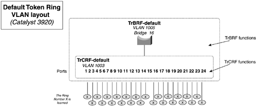
Token Ring Bridge Relay Function ( TrBRF ) and the Token Ring Concentrator Function (TrCRF)The Token Ring bridge relay function (TrBRF) functions like a multiport bridge. Its purpose is to bridge rings. The rings that it bridges are called Token Ring concentrator relay functions (TrCRF). (These probably would have been called virtual rings, but that name was already taken.) Multiple TrCRFs can attach to a single TrBRF, much like multiple rings can attach to a single bridge. TrCRFs can exchange data through source-route bridging (SRB) or source-route transparent bridging (SRT). If you are not familiar with these bridging technologies, you might want to read these sections of Chapter 13, "Configuring Bridging and Data Link Switching Plus." The TrBRF spans Catalyst switches, much like a Ethernet trunk. This allows TrCRFs on different Catalysts to belong to the same bridge number. Remember that the TrCRF is "the ring." A TrBRF must be created before a TrCRF is defined. Each TrBRF is identified by a bridge number and VLAN ID. When you create a TrCRF, you identify it with a ring number and another unique VLAN ID. The TrCRF must be assigned to a parent TrBRF. Figure 2-18 illustrates the TrBRF TrCRF relationship in the Catalyst 3920. The trbrf-default and the trcrf-default are the actual default TrBRF and TrCRF for all Catalyst switches. Think of them like an abstract VLAN 1 on Ethernet switches. Like Ethernet switches, Token Ring switches were designed to be "plug-and-play" on smaller networks. By default, all ports will be assigned to the trcrf-default, and the trcrf-default has TrBRF as its parent. Figure 2-18. Default TrBRF TrCRF Relationship The concept of default TrBRFs and TrCRFs made LAN migrations from shared hub/MSAU environments easy. Out of the box, a Token Ring switch could be deployed without any configuration in place of a hub or MSAU. Like Ethernet switches ports that reside on the same default VLAN, Token Ring ports reside on the same default ring and bridge. Table 2-16 lists the default VLAN settings for Cisco switches. Table 2-16. Default VLAN Settings
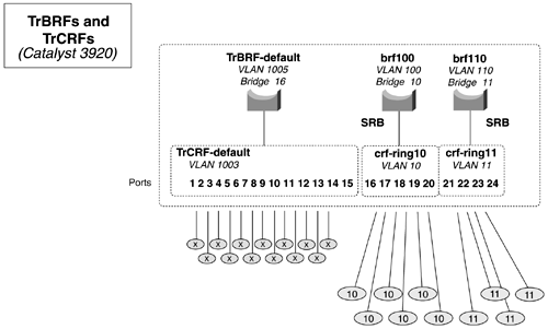
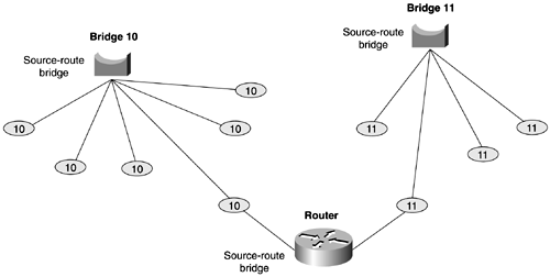
Figure 2-19 diagrams the logical layout of a Token Ring switch. Two TrBRFs were created on the switch. TrBRF brf100 will be bridge 10. This BRF is the parent to the TrCRF crf-ring10, which will be ring 10. All ports on the switch assigned to this CRF will be in ring 10. In this figure, ports 16 to 20 will all be on ring 10. The second TrBRF is used to link bridge 11 to ring 11; ports 21-24 will be on ring 11. Figure 2-19. Logical TrBRF TrCRF Relationship When this switch is configured, you will have two bridging domains. Figure 2-20 shows another conceptual view of the same configuration, represented in a more traditional fashion. Figure 2-20. Conceptual View of TrBRFs and TrCRFs For the bridging domains to communicate, they need to be connected with another source-route bridge, usually in the form of a router. Figure 2-21 illustrates how the two domains can be linked with a router. If the network were transporting a bridged protocol such as SNA, the router could be configured for source-route bridging, and the two domains could be source-route bridged. If the network were transporting a routed protocol such as IP, the router would be configured to "route" traffic between the two domains. Figure 2-21. Linking Two Token Ring Bridging Domains |
| < Free Open Study > |
EAN: 2147483647
Pages: 283


