Managing Objects
|
Managing objects is probably the thing you'll be doing most often as a firewall administrator. Luckily for you, Check Point has made this task much easier than you might think. While there is still a lot of information needed to set the foundation for your rule base, you needn't put forth a great deal of effort to get that information into a useable format.
Your first task is to log into the FW-1 GUI management client. On a Windows system, simply start the Policy Editor or your GUI client by double-clicking its icon. On a Unix system such as Solaris or AIX, execute the fwpolicy command found in $FWDIR/bin. You'll be presented with a login window, as displayed in Figure 13.1. Note that if this is the initial connection from a GUI client, FW-1 will present the management server fingerprint. This is used as a security measure to enable you to validate the identity of that management server.
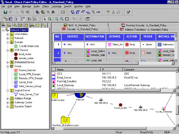
Figure 13.1: Policy Editor
Once you have logged into the GUI, you'll see a lot of information. Don't worry; you can easily customize this default view to show you just what you need. You can also add or subtract from this view as needed. A couple of changes have been made from previous versions of the policy editor. Figure 13.1 shows you the new default view.
The windowpanes are called (from left moving clockwise) the Objects Tree, Rule Base, Objects List, and Topology Map. You can toggle which one is displayed by selecting View from the Policy Editor menu, as displayed in Figure 13.2.
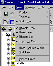
Figure 13.2: View Selection
The Objects Tree gives you a concise and orderly view of the defined objects of each available type. If your manager asks which networks are defined, here's the place that will give you the quickest answer. Next is the rule base. This enables you to instantly sum up the totality of what your firewall is enforcing, but it also enables you to quickly view Network Address Translation (NAT), Quality of Service (QoS) and Desktop Security rule information. Below the rule base you'll find the Objects List, which presents a little more detail than the Objects Tree about your defined objects. The final pane in this window is our "belle of the ball," as it were. New in FireWall-1 NG (assuming you've purchased the Visual Policy Editor) is the Topology Map. This gives you a handsome network map showing the interconnections of all your defined objects. Figure 13.3 shows the Topology Map pane enlarged to full screen.
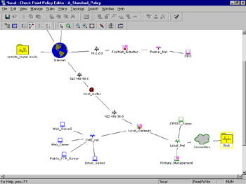
Figure 13.3: Topology Map
The neat thing is that this map is completely interactive. You can rearrange the placement of the objects and even query them for information, and alter their configuration.
Network Objects
Network objects are, as the name states, simply the objects within your network. An object can be a network range, a group of users, or a single workstation, as examples. Objects can also be groups of other objects, allowing a hierarchical layering and a more concise rule base. More importantly, you must have properly defined the objects of interest within your network before using them in a FW-1 rule.
Network objects can be defined in any of several ways, with the most common method being through the Network Objects Manager, which is shown in Figure 13.4. This GUI window enables you to create, delete, and alter all of the various types of network entities. To access this screen, select Manage | Network Objects from the Policy Editor GUI.
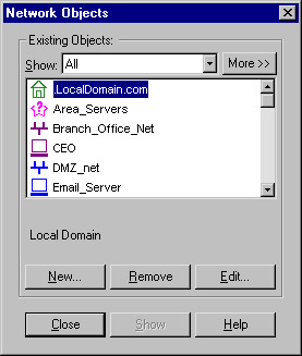
Figure 13.4: Network Objects Manager
Workstation
The workstation object defines a single computer, and contains many options. This computer may be a simple workstation, a VPN-1/Firewall-1 system, a third-party VPN device, a gateway, a host, or any combination of these. This flexibility comes with a slight increase in complexity. The Workstation properties page contains a great many more options than its counterpart in previous versions of FW-1, but luckily there is intelligence built in to the window. The branches on the left become visible as they are needed. A simple workstation will have limited options, but the choices expand when dealing with Check Point installed products. Table 13.1 defines some of the more common configurations and their displayed options.
| VPN-1/FireWall-1 | Floodgate-1 | Second Management Station | Log Server | UserAuthority | Web Plugin |
|---|---|---|---|---|---|
| General | X | X | X | X | X |
| Topology | X | X | X | X | X |
| NAT | X | X | X | X | X |
| VPN | X | X | |||
| Authentication | X | X | |||
| Management | X | X | X | X | |
| Advanced | X | X | X | X | X |
The General configuration window, as shown in Figure 13.5, enables you to associate a system name and an IP address with this object. If the name is resolvable via something like DNS, then you can use the Get Address button to retrieve the IP address, or else you can type it in manually. The comment field is optional. In common with all FireWall-1 objects, you can assign a color to the object. The remaining fields have special meanings when selected, which impact the way VPN-1/FireWall-1 interacts with them.
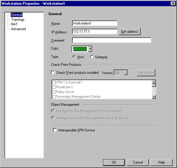
Figure 13.5: Workstation Properties, General Window
-
Type Select if this device is a gateway or a host. Note the caution in the sidebar relating to gateway address specification. If this device is a gateway, then rules selected as installed on gateways will be enforced on this system.
-
Check Point Products This enables you to identify the workstation device as running Check Point software. If the checkbox is selected, the options in Object Management will become active, as will the Get Version button. Interoperable VPN Device is an exclusive selection, thus it will become grayed out. Also, the Management, Authentication and VPN branches will become visible, and sub-menus will become available under the Advanced branch. You will also see the Secure Internal Communication option, which enables you to establish the link between Check Point installed products. Figure 13.6 illustrates the properties window as it appears when this option is selected.
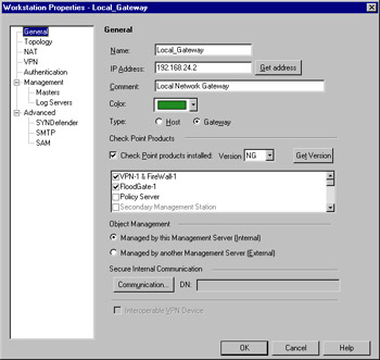
Figure 13.6: Workstation Properties with Check Point Products Installed -
Object Management Here you specify whether the Check Point product specified on the workstation object is internal (managed) or external (not managed) to the management server.
-
Interoperable VPN Device This enables you to denote this object as an interoperable VPN unit. This means that, while no Check Point software is installed on the device, it is still capable of performing IKE encryption for the purpose of establishing a VPN. If this option is checked, you'll have access to the VPN branch of the Workstation Properties. Interoperable VPN devices are only allowed to use IKE encryption, unlike VPN-1/FW-1 VPN setups.
What's in a Name?
The only requirement for the Name field is that it must be unique. However, it is strongly recommended that you use an actual resolvable name. It is also strongly recommended that you include the hostname to address mappings in your systems host files. These files can be found in the following locations:
-
For Unix systems, edit the /etc/hosts and /etc/networks files
-
For Win32 systems, edit the %SYSTEMDIR%\system32\drivers\etc\hosts and %SYSTEMDIR%\system32\drivers\etc\networks
This will ensure the proper function of the Get Address function. Be wary, however, to maintain these files. Hostname and address changes could lead to potential exposure if not done properly.
Also, if the workstation you are defining is a gateway (a multi-homed system that is able to pass traffic between its interfaces), and you are using IKE encryption, be sure to include specify the outside address. If you fail to do so, IKE encryption will not function properly!
Network
The network object defines a group of hosts or, more specifically, a network range such as a subnet. When defining individual systems as Workstations becomes too tedious or otherwise untenable, it is quite easy to arrange them with the network object type. To create a new Network object, select New | Network from the Network Objects management window. This will present you with the panel as shown in Figure 13.7.
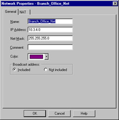
Figure 13.7: Network Properties—General Window
The General window allows some simple configuration information to be entered, such as IP address, netmask, and a comment. Note that the portion of the IP address that specifies the host is ignored. We're assuming you are already familiar (at least slightly) with IP subnetting. In the example panel, the network is 10.3.4.X, with a 24-bit subnet, producing a mask of 255.255.255.0. In this case, you enter the host portion as a zero. Keep in mind, though, that the host portion might not always be set as zero, and might not always fall on a tidy boundary. For example, you might have a network address of 10.3.4.128, with a subnet of 255.255.255.128. When in doubt, consult your local networking expert. As with all object types, a color can be assigned as well. The last field, Broadcast address:, is used to specify whether the broadcast address will be included within the defined network. The broadcast address is defined as the last possible IP within that range.
The NAT panel is the familiar one, which includes the option to establish automatic translation rules. Nothing extraordinary here.
Domain
Another method to group hosts by commonly used techniques is to use the domain object. A machine is determined to be within the domain if a reverse DNS lookup on the machine's IP address yields the proper domain information. Figure 13.8 illustrates this panel, which is accessed by selecting New | Domain from the Network Objects management window.
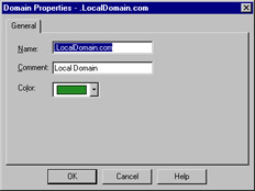
Figure 13.8: Domain Properties
Notice that in the above example the domain name begins with a period. You may be wondering how FW-1 knows what to do with a domain object. When a domain object is used in the rule base as a source or destination, FW-1 will attempt to do a reverse DNS lookup (that is, getting the name for a specified IP) on the appropriate portion of the incoming packet. If the lookup yields the domain information, then you have a match. It is probably obvious that if there is no reverse record, the object will be useless. It is also possible that, through DNS poisoning, this sort of object could lead to a security breach. For these reasons and others, Check Point does not recommend the use of domain objects in your rule base. If you decide to use them, use them as close to the bottom of the rule base as possible.
OSE Device
Open Security Extension technology allows FW-1 to manage third-party devices that support these extensions. Most notable among these devices are Cisco routers running IOS v9 and later. The number of devices that you may manage depends on your license. The configuration for an OSE compliant device features three windows. To create a new OSE Device, select New | OSE Device from the Network Objects management window. Figure 13.9 illustrates the General window.
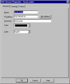
Figure 13.9: OSE Device—General Window
This window enables you to specify some of the basic information about the device, specifically the IP address, name, comment, and device type. The device type may be any of the following:
-
BayRS
-
Cisco
-
3Com
When a device from this category is managed by the firewall, access control lists are generated based on the security policy and downloaded to the firewall. As with other object types, the Get address button will attempt to resolve the specified name to an IP address, saving you that one step.
The topology window is identical to that of its counterpart for the other devices. The main caveat is that at least one interface must be defined (as opposed to, say, a simple workstation) or the ACL entries will not be created successfully. Anti-spoofing and its kin are also defined by editing the interface properties, just as with a workstation. However, there are some additional steps to take, which are accomplished by editing the information on the Setup window.
The Setup window varies depending on the OSE Type specified on the General window. The window as displayed with a Cisco router is displayed in Figure 13.10.
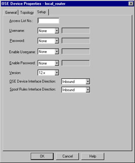
Figure 13.10: Cisco OSE Setup Window
The fields displayed on this window have the following meanings:
-
Access List No. The number of the ACL that will be applied.
-
Username This is the exec mode username that will be used for initial access to the device. It, along with the remaining drop-down lists, can be set to None, Known, or Prompt. If set to Known, the gray box to the right will become active and allow the entry of a username.
-
Password Enter the password associated with the exec mode username.
-
Enable Username The name, if any, of a user with privileged exec access.
-
Enable Password The password associated with the privileged username.
-
Version IOS version installed on this router.
-
OSE Device Interface Direction The direction in which to enforce the security policy. This can be Inbound, Outbound, or Eitherbound.
-
Spoof Rules Interface Direction The direction in which to enforce anti-spoofing behavior. This can be Inbound, Outbound, or Eitherbound.
The fields for the 3Com and Bay devices are similar in their requirements, and the security policy is enforced in an identical manner.
Embedded Device
An embedded device is defined as a device on which a VPN/FW-1 module or Inspection module is installed. This type of object is restricted to two types (as defined in the Type field) with those being Nokia IP5x and Xylan with the supported platforms being Ramp and Xylan.
The configuration is pretty straightforward, with the common rules applying. Define the name, IP address, and an optional comment. Then specify the type, and select VPN-1 & FireWall-1 installed if applicable. You must also define your license type. Figure 13.11 illustrates the configuration panel. To open this panel, select New | Embedded Device.
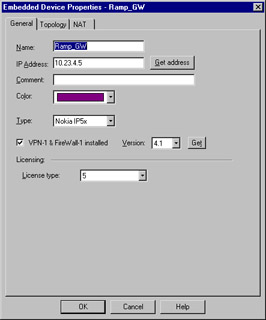
Figure 13.11: Embedded Device General Properties
Group
The Group object can be used to manage other objects of dissimilar types. There are three types of groups that you may define within FW-1. To create a new group, select New | Group from the Network Objects management window. The group types are as follows:
-
Simple Group
-
Group with Exclusion
-
UAS High Availability group
A simple group is just that. Simple. It is a collection of network devices. The second group type, Group with Exclusion, allows you some granular control over the contents of a group. If you are working in a network with a flat topology, for example, you may be in a situation where there isn't much physical separation within this network. A group of this type enables you to force some structure here. Figure 13.12 illustrates a simple group.
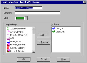
Figure 13.12: Group Properties
A Group with Exclusion is slightly different than a Simple group, with the difference being that you specify a major group, defined by Check Point as an "outer group." This will be the group that is included for this definition. You then specify minor, or inner, groups. These will be the groups culled out and excluded from the major group.
Logical Server
The logical server group (available by selecting New | Logical Server from the Network Objects window) enables you to group like servers (FTP, HTTP, SMTP, etc) to be treated as one and used in a sort of resource sharing, or server pooling. Note that this is an optional feature and may not be included with your FW-1 installation. Workload is distributed among these servers in a user-configurable manner. Figure 13.13 shows the configuration options for this object type.
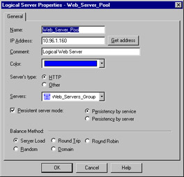
Figure 13.13: Logical Server Properties Window
As usual, the name must be entered, and, if resolvable, the Get address button can be used to gather the associated IP address. A special note is in order here, specifically regarding the IP you'll select. This address should be that of a non-existent server located on the same network as the destination servers, but can also be that of the FireWall-1 module. Think of this IP as a virtual IP address. It will be used by the clients to connect to the Logical Server group, and therefore cannot belong to any one member of that group.
The Server's Type feature really is poorly named. This actually defines the method of load balancing, or even more specifically, the type of algorithm used. The two methods behave very differently. For example, with HTTP selected, only the initial connection will be handled by the logical server address. A redirection is sent to the client informing his or her browser of the new IP (that of the selected destination server), and the remainder of the conversation goes forth without the intervention of the firewall module. If Other is selected as the type, address translation is performed and the conversation is balanced per connection, with the firewall module constantly involved, unless Persistent Server mode is checked.
The Servers section enables you to select the server group that will make up this logical group. If selected, Persistent server mode allows some fine-tuning of the balancing mechanism. When enabled, you can enforce connection persistence, meaning you can force packets from an established flow to continue to a single destination. This is very useful for something like an HTTP conversation when using Other as the server type. You can select between two modes here, Persistency by service and Persistency by server. The main difference between the two is that, when the former is selected, only connections to a single server for a single service will have persistency enforced, while in the latter any service on a specific server will be impacted.
The final settings define the type of balancing to be performed. The Balance Method has several possible options.
-
Server Load FW-1 sends a query, using port 18212/UDP, to determine the load of each server. There must consequently be a load-measuring agent on each server to support this method.
-
Round Trip FW-1 sends a simple ICMP ping to each server. The fastest round-trip time is chosen as the preferred server. This lacks somewhat, in that the ping is from the firewall to the server, and may not be optimal from a remote client (remember, the servers need not be centrally located to participate in a server group). Also, a ping doesn't tell you that the HTTP daemon has crashed on the server. As long as the server is up and on the network, regardless of the status of any of its services, traffic will be sent to it.
-
Round Robin FW-1 selects sequentially from a list. This is among the simplest methods.
-
Random FW-1 selects randomly from a list.
-
Domain FW-1 attempts to select the closest server to the client, based on domain naming convention. This method is not recommended.
Address Range
An address range defines a sequential range of IP addresses for inclusion with your rule base. An address range is similar in use to a network object, with the major difference being that you specify a starting and ending IP address instead of a network number and subnet mask. Figure 13.14 illustrates the General panel for this object type, which is available by selecting New | Address Range from the Network Objects management window. As usual, the NAT panel features no special information and is the same as that found on most other object types.
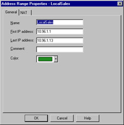
Figure 13.14: Address Range Properties Window
Gateway Cluster
A gateway cluster is a grouping of machines running VPN-1/FW-1 that is grouped together as a means of fail-over support. Clustering is a complex subject, and configuring it is much more detailed than the majority of other object types. First, you have to visit the Global Properties and, under the Gateway High Availability branch, place a checkmark in the setting to Enable gateway clusters.
The next step is to create your workstation objects. In order to support clustering, you must have at least three objects, two of which must be firewall modules, and one a manager. The workstation object should be created as normal for a machine with FW-1 installed. It is important that the interfaces are properly defined, as anti-spoofing is required for proper high-availability function. Next, you create a new gateway cluster object. The General panel is illustrated in Figure 13.15. You'll access this panel by selecting New | Gateway Cluster from the Network Objects management window.
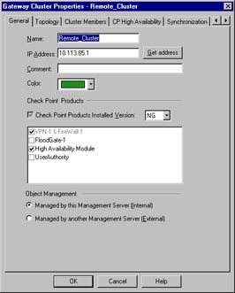
Figure 13.15: Gateway Cluster—General Panel
This panel allows the initial configuration for the cluster. The name and IP address are defined here, as are the specific Check Point products that will reside within this cluster. Also, you can specify whether you or another party manage the cluster. You also can specify, on the topology panel, which addresses reside behind this cluster. This is similar to the features on a workstation object's interface properties topology panel.
Dynamic Object
A dynamic object is perhaps the most interesting object type supported on FW-1. It is also one of the most useful in a large enterprise. This object type enables you to define a logical server type, one in which the actual IP address will resolve differently on each FW-1 machine. This enables you to create rules referencing "mail server" and distribute that policy to several different FW-1 machines, all of which will resolve "mail server" as the proper machine within their realm. Figure 13.16 shows you the basic configuration window, which you can see by selecting New | Dynamic Object from the Network Objects management window.
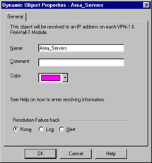
Figure 13.16: Dynamic Object Properties Window
The real key to a dynamic object is the dynamic_objects command. This command is run on the firewall module where the name will be resolved, and enables you to specify the values to which it will resolve. Table 13.2 describes this command and its options.
| Option | Explanation |
|---|---|
| -o <object name> | Specify the object name to work with. This option is often used with operators such as –a to add addresses to an existing object. |
| -r <address range> | Specify an address range. |
| -a <address range> | Add address of <range> to object. |
| -d <address range> | Delete addresses from the object. |
| -l | List all dynamic objects. |
| -n <object name> | Create a new dynamic object; assuming the VPN-1/FW-1 process hasbeen stopped. |
| -c | Compare the defined dynamic objects to those defined in theobjects.C file. |
| -do <object name> | Delete the specified object. |
Services
The services objects give you a finer level of access control as compared to exclusive use of network entities. With the service object, you can define protocol specific information, like protocol in use (TCP, UDP, and so forth), and port numbers. FW-1 comes preconfigured with many of the more common services in use today, and further enables you to create custom services based on your unique needs.
To add, modify, or delete services, access the Services window by clicking Manage | Services. From here, you will be able to act on the following service types.
TCP
The TCP service object enables you to define a basic TCP service. Figure 13.17 illustrates this service type, using the domain-tcp (DNS) service as an example. To bring up this window, select New | TCP from the Services management window.
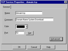
Figure 13.17: TCP Service Properties
The information required for this service is very limited (which is nice when you have to define a lot of them!). Besides a name and comment, all you have to enter is the destination port number. This can be a specific port, as in Figure 13.17, a range (e.g. 1024-1028), or a greater-than/less-than definition (e.g. <56). There is also an Advanced button, which displays the window as shown in Figure 13.18.
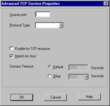
Figure 13.18: Advanced TCP Service Properties
The Advanced settings enable you to specify a source port, and allow for the same modifiers as in the General panel's port specification. You can also specify the protocol type, which impacts which security server will provide things like content security for this service. The checkbox marked Enable for TCP resource, if checked, enforces screening using a UFP server, mitigating the intervention of a security server. The next item, Match for 'Any' allows connections using this service to be matched when a rule is crafted with 'Any' as the service. The Session Timeout is a local setting meant to allow override of the global session timeout. The inclusion of the timeout in the GUI is a nice change for FW-1 NG. In previous versions, setting a per-service timeout required manual editing of the base.def file, which is obviously a bit more involved.
UDP
The UDP service object enables you to define a basic UDP service. An example of this is the TFTP service. UDP tracking poses a problem for many firewalls, especially circuit level gateways. Since UDP is connectionless, it's generally an all-or-nothing approach to security. Whole port ranges are often opened to allow UDP traffic, which is not a very nice notion. With FW-1, a second mechanism has been designed to keep track of a virtual "connection."
The General properties are identical to those for TCP, as seen in Figure 13.17. The Advanced options are slightly different, and are shown in Figure 13.19.
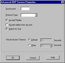
Figure 13.19: Advanced UDP Service Properties
As with the TCP settings, we are able to specify a source port and a protocol type. Additionally, we have the familiar checkboxes, but this time with slightly different values. These are as follows:
-
Accept Replies If checked, allows for a bi-directional communication to take place.
-
Accept replies from any port Allows the server to reply from any port. An example of the need for this is the TFTP service.
-
Match for 'Any' Allows connections using this service to be matched when a rule is crafted with 'Any' as the service.
RPC
RPC services are usually tricky for a firewall administrator. RPC-based connections do not use a fixed port number, so allowing these types of connections is either an all-or-nothing exercise. Usually, administrators choose to block all RPC connections on their external firewalls, while being far more permissive within their network boundaries.
To alleviate this potential risk, FW-1 transparently tracks RPC ports. Application information is extracted from the packet in order to identify the program used. FW-1 also maintains a cache that maps RPC program numbers to the assigned port numbers. The configuration panel, viewed by selecting New | RPC from the Service management window, is shown in Figure 13.20.
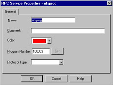
Figure 13.20: RPC Service Properties
ICMP
ICMP is used for things like network troubleshooting and discovery. Unfortunately, attackers looking to gain information about you can also use it. For this reason, many sites decide to block all ICMP traffic. This isn't really necessary, and may cause more problems than it solves. You can, using FW-1, pick and choose the specific ICMP types (and even sub types, or "codes") allowed. Table 13.3 details some of the more useful ICMP types, their associated codes, and their meanings, as defined by the IANA (www.iana.org/assignments/icmp-parameters).
| ICMP Type | ICMP Code | Explanation |
|---|---|---|
| 0 | Echo (ping) reply | |
| 3 | Destination unreachable: | |
| 0 | -network unreachable | |
| 1 | -host unreachable | |
| 2 | -protocol unreachable | |
| 3 | -port unreachable | |
| 4 | Dropped because DF (do not fragment) bit was set, fragmentation needed | |
| 5 | Source routing not allowed or otherwise failed | |
| 4 | Slow transmission rate | |
| 5 | Better network path available: | |
| 0 | -for entire network | |
| 1 | -for specific host | |
| 2 | -for tos and entire network | |
| 3 | -for tos and specific host | |
| 8 | Echo (ping) request | |
| 11 | Time exceeded for reason: | |
| 0 | -TTL reached 0 in transit | |
| 1 | -fragment reassembly time exceeded | |
| 12 | Bad IP header |
Figure 13.21 shows us the configuration panel for an ICMP service. Using Table 13.3, you can see how simple it would be to create services, and thus rules, to allow the beneficial types of ICMP while excluding those that may do you harm.
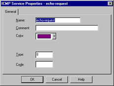
Figure 13.21: ICMP Service Properties
Other
Often called user-defined services, this is a catchall for whatever is missing. Its presence gives you a great deal of flexibility, but requires at least a familiarity with the inspect language. The General panel is similar to that found in its cousin objects, allowing you to define a name, add a comment, and assign a color. It also enables you to define the protocol identifier. This is a very important field, as it is the key to matching against the incoming traffic. Figure 13.22 shows you the General panel for this service type.
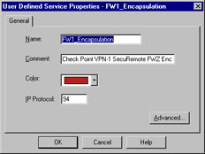
Figure 13.22: User-Defined Service Properties—General Panel
Clicking the Advanced button brings up a screen that allows the entry of the most crucial part of this object, the Match field. This field is a snippet of inspect code that will be used to check the incoming packets. It can, therefore, be as complex as you can imagine. This makes the user-defined object a truly powerful tool for the enforcement of very specific requirements.
Group
The group object enables you to combine different protocols. This can be used, for example, to define a service whose individual parts must also be separately defined. Ping is a good example. It consists of an echo request and an echo reply. These can be defined and then combined into a group, and that group used in your rule base. Figure 13.23 displays the configuration window, which is accessed by selecting New | Group from the Services management window.
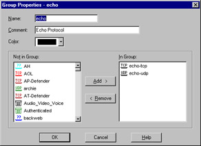
Figure 13.23: Group Properties
DCE-RPC
This service type works in a similar fashion to the RPC service, in that it tracks DCE-RPC based connections, extracting the information from the packet and creating a virtual session whose information is stored in a local cache. When you define the DCE-RPC service, you will be asked for the UUID for the specific interface as well as the protocol type. Figure 13.24 illustrates this panel.
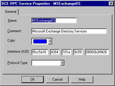
Figure 13.24: DCE-RPC Properties
Resources
Resource objects are used to configure Content Security on FW-1. Content security includes support for the HTTP, FTP, and SMTP protocols. FW-1 provides this support by using the FW-1 Security Servers. For each connection established through the FW-1 Security Servers, you are able to control access on a granular level according to protocol specific information unique to a specific service. This includes URLs, file names, FTP commands, and so on.
Uniform Resource Identifier
A Uniform Resource Identifier (URI) defines how to access resources on the Internet. Most of us are familiar with the URI by another name: URL. Which term you use is often a matter of tossing the dice, as there is dispute even among the standards developers as to which is more proper.
URI for QoS
Another type of URI object is the URI for QoS, which is used when defining a rulebase for FloodGate-1. This resource type allows the security administrator to classify certain URIs as part of a QoS policy. This object type is fairly simple to create. You'll need to define a name, comment, and select the color for the object. Additionally, you will need to define a Search for URL. This specifies the URL that will trigger a match, and it can be as specific as a complete URL, or as general as *.jpg, which would match any JPEG file.
SMTP
The SMTP resource defines the methods used by the FW-1 to handle incoming or outgoing e-mail. There are many options, including the ability to remove active scripting components, rewriting fields in the envelope (such as To: or From:) or filtering based on content. The configuration of this resource type is similar to that of the URI, including the ability to use a CVP server.
FTP
An FTP resource is defined in order to enforce content security for FTP connections. We like to use this resource to define the verbs or methods that will be allowed through my firewall. For example, if we have an FTP server that is publicly available for downloading, we can back up the system administrator and deny the ability to PUT.
Open Platform for Security Applications
The Open Platform for Security (OPSEC) object defines for you a means of interacting with a third-party developed security application. These applications add extended functionality to the FW-1 installation. Some examples include virus scanning, content filtering, and intrusion detection. OPSEC allows FW-1 to send its data stream to other applications, and it also allows those applications to send data to the firewall, for example, log entries via the ELA or status via AMON interfaces.
Servers
A server is a host computer running a specific application or service. The server object is the representation of that relationship.
Radius
A RADIUS server is used to provide authentication services. While originally used for remote access services, it is also now commonly used for things like routers and firewalls. To define a radius server, select Manage | Servers from the policy editor drop-down menu and then select New | RADIUS. The configuration appears as in Figure 13.25.
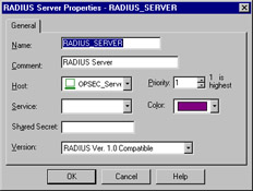
Figure 13.25: RADIUS Server Properties
The RADIUS server object is configured in a way that is fairly common with the other server types. After defining the name, adding a comment, and selecting the associated color, you'll need to specify the Host that this RADIUS server is running on. You'll also need to assign a Priority. The priority is used to determine the preference for an individual server when more than one is available for contact, for example, when the server is assigned to a RADIUS group.
The next step is to define the Service, which is the obvious choice of RADIUS. The Shared Secret must be entered in order to establish communication between the firewalled object and the RADIUS server. Consequently, it must be the same on both devices. The final step is to select the proper version from the Version drop-down menu.
Radius Group
A RADIUS group is used to form a group of RADIUS servers. These servers are then available for use as a single object, with authentication services being performed by the server with the highest priority (e.g. the lowest number). Unlike most other groups, server groups such as this may not contain any dissimilar entities.
TACACS
A Terminal Access Control Access Control Server (TACACS) server is another one of your handy access control methods. The definition of this object shares the same generalities of the other server entities, those being name, comment, color, and host. Once these are defined, you have only to specify if the server is running TACACS or a TACACS+, enter a secret key, if necessary, for TACACS+, and select the appropriate Service from the drop-down menu. (Note that you won't have to select a service with TACACS+.) This panel is illustrated in Figure 13.26.
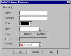
Figure 13.26: TACACS Server Properties
Defender
The Defender server type defines an object running AXENTs Pathways Defender server. This is another authentication method available to you as a FW-1 administrator, and is very easy to incorporate. Besides your four familiar fields of Name, Comment, Color, and Host, you are also able to specify a backup host. Then all that remains is to enter the Agent ID, as defined on the Defender server, and the Agent Key, which is used to encrypt the communication with the Defender server, and is also specified in the Defender server's configuration.
Lightweight Database Access Protocol Account Unit
The Lightweight Database Access Protocol (LDAP), is used for a bevy of purposes. With regards to FW-1, this server object is used for the purposes of user management. A full discussion of the workings of LDAP is beyond the scope of this book but we'll assume if you are configuring an LDAP object, you have access to an existing LDAP server and the necessary information. Figure 13.27 illustrates the General panel for LDAP configuration.
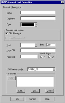
Figure 13.27: LDAP Account Unit Properties
Certificate Authority
We've all heard the buzz about PKI, now here's your chance to jump on the bandwagon. The inclusion of a certificate authority in your security infrastructure enables you to use certificate-based authentication and encryption that eases (or perhaps shifts) the administrative burden of VPN development.
There are three tabs for the Certificate Authority object, with the first being the very simple General tab. The associated panel allows the standard configuration information of Name, Comment, and Color, as well as the ability to specify the Certificate Authority via a drop-down menu. You'll have a few choices in this drop-down, with your selection determined by what is available to you. The contents of the second panel depend on the selection in this drop-down box.
The contents of the second panel vary, but generally allow for the importing of a configuration from the PKI server and the importing of the actual certificate. You may also be able to specify the source of the Certificate Revocation List (CRL).
The Advanced panel deals with the CRL for this server; specifically, it configures the desire to cache the CRL and when to fetch a new CRL. You can also assign what branches are to be allowed.
SecuRemote DNS
SecuRemote DNS is an internal server type that is used to resolve private addresses to names. SecuRemote DNS replaces the need to create a dnsinfo.C file on the management server's $FWDIR/conf directory. This is a nice change. You will, however, still need to edit $FWDIR/lib/crypt.def though, adding the line #define ENCDNS to enable SecuRemote users to download this information along with their topology.
Configuration of this server type is fairly straightforward. You have two tabs: General and Domains. The General panel allows the configuration of the Name, Comment, Color, and Host. As usual, the host must have previously been defined as a workstation object.
The Domains panel lists the domains that are included for resolution, as well as something called a Maximum Label Prefix Count. This count defines the number of prefixes that will be allowed for the specific domain. For example, if the domain is .edu, then troll.gatech.edu has two prefixes. If the maximum prefix count was one, this domain would not resolve.
Internal Users
The ability to define users on the firewall is a nice feature, but it is also rather administratively intensive. The benefit is that you can select specific users as the source for traffic in a rule. The downside is you have to define these users. Fortunately, Check Point has simplified this process somewhat with the ability to define generic user templates. The use of LDAP as an external source of user information is also supported, which greatly decreases the workload redundancy of a firewall administrator.
The first step is to bring up the Users interface. This is accessed by selecting Manage | Users from the policy editor menu. This window is used to define and modify users, and also to install the user database to the VPN-1/FW-1 systems on which this policy is installed.
Time
Time objects are just that. These objects enable you to schedule events, restrict connections, or simply quantify a time period. For example, you can restrict Web browsing not only to specific sites, but also to specific times. There are three possible object types to select from. You can specify a time, a scheduled event, or a group of one or more of these types. To create a new time object, simply select Manage | Time from your policy editor window.
The time object is used to restrict the application of rules to specified times. There are two panels to this object: General and Days. The General panel allows the standard settings, as well as up to three time ranges. These ranges specify the time spans in which this object would be applicable. The second panel, Days, enables you to enforce a finer-grained access control on the time object. We can specify days of a week, or a specific date, or a numbered day in each month. Figure 13.28 illustrates the Days panel.
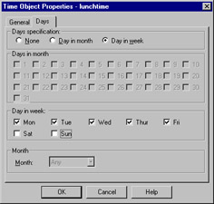
Figure 13.28: Time Object—Days Panel
Group
A group is formed by the combination of several time object types, and can be used to simplify time-based rules. Instead of using multiple rules, you can create a group of time objects and assign this to a single rule. Creating a time group is similar to the other group types, and consists of assigning a name, comment, and color and then moving time objects from the Not in Group list to the In Group list.
Scheduled Event
A scheduled event is most often used for administrative purposes, such as scheduling log changes. Configuration is simple, with the only interesting field being the specification of the time at which the event will be triggered. You can also, as with the time object, schedule the repetition frequency of the object. For example, when you define your Management machine, you have access to the Management branch of the Workstation properties. One of the fields, Schedule log switch to:, requires the use of a time object as its option.
Virtual Link
A Virtual Link is a path between two VPN-1/FW-1 modules or FloodGate-1 Modules. Virtual Links are defined in the Policy Editor, and can be given Service Level Agreement (SLA) parameters. They can then be monitored using Check Point Traffic Monitoring. To add a new Virtual Link, select Virtual Links from the Manage menu in the Policy Editor.
There are two panels to be configured. The General panel defines the name, etc., for the link, and also enables you to define the endpoints and to optionally activate the link.
The SLA Parameters panel, shown in Figure 13.29, enables you to specify the criteria that will be used to measure the integrity of the link. Thresholds are defined in three directions of traffic. You can specify the Committed Information Rate (CIR) for traffic point A to point B, and the reverse as well. You can also specify a maximum round trip time (RTT) for bi-directional communication, and optionally log the SLA statistics.
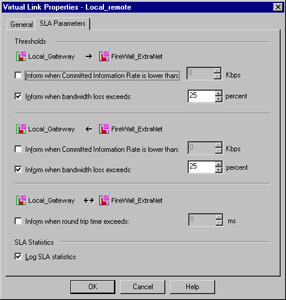
Figure 13.29: Virtual Link Properties—SLA Parameters
|
EAN: 2147483647
Pages: 240