Section 15.1. Basic Definitions and Techniques
15.1. Basic Definitions and TechniquesA simple operation of data multicasting can be viewed through a transmitting host and several receiving hosts . Instead of forcing the source host to send a separate packet to each destination host or user , the source needs to be able to forward a single packet to multiple addresses, and the network must be able to deliver a copy of that packet to each group of receiving hosts or users. Hosts can then choose to join or leave this group without synchronizing with other members . A host may also belong to more than one group at a time. Figure 15.1 shows a typical packet multicasting in different layers. As shown, multicasting a packet could involve almost all layers of a communication network. A multicast task can be performed at the application layer, where two hosts can directly connect through a copy of the source. Meanwhile, a message can be multicast systematically through the physical, link, and network layers . Figure 15.1. An IP multicast model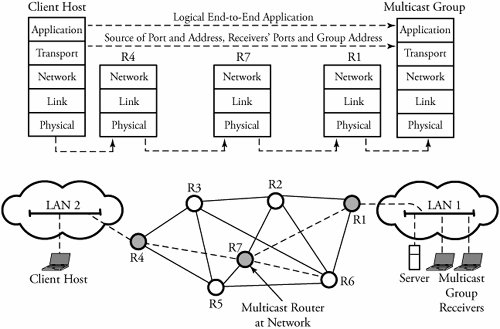 With the use of a robust multicasting protocol, a network reduces traffic load by simultaneously delivering a single stream of information to potentially thousands of recipients. An example is the distribution of real-time stock quotes and news. In such cases, the application source traffic is delivered to multiple receivers without burdening the source or the receivers and using a minimum amount of network bandwidth. Among the challenges of implementing data multicasting are the following two, which are especially relevant in large networks:
Tight real-time components require a constant flow of data and have a very low jitter tolerance. To this end, corrupted data frames are often dropped rather than retransmitted. In this context, one would like to see a dynamic multicast system that adapts to deletions and additions of ongoing data over time. In the multicast service, we want to make copies of data at or near a source with only one access to the transport media. But having copies of packets floating around raises issues of congestion. However, copying packets near destinations risks losing all copies of packets if the original packet is lost at that location. 15.1.1. IP Multicast AddressChapter 2 discussed IP addressing, notingh that multicast packets are of class D. The first four bits a class D IP address identify the class of the address, where 1110 represents a multicast address. The remaining 28 bits identify a particular multicast group. Thus, multicast addresses can range from 224.0.0.1 through 239.255.255.255, and 2 28 is the maximum number of multicast groups that can be formed simultaneously. Multicast addressing is an open issue at both the network and the link layers. As shown in Figure 15.2, a multicast address from the network layer needs to be mapped to multicast addresses of the data-link layer when mapping between IP multicast and an Ethernet multicast address is performed. Note that the space for the Ethernet multicast address is smaller than that for an IP multicast address. Therefore, the first 23 bits of the IP multicast address are placed into the first 23 bits of the Ethernet multicast address field. The 25 bits left in the Ethernet multicast address are assigned a fixed value. Note also that a 1-bit field, M , represents the two cases: the Internet multicast with 0 and any other applications with 1. Figure 15.2. Mapping between IP multicast and Ethernet multicast addresses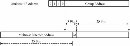 15.1.2. Basic Multicast Tree AlgorithmsMulticast group membership is a dynamic function, so any host can join or leave an IP multicast group at any time. Multicast packets are also subject to loss, delay, duplication, and out-of-order delivery. In WANs, data multicast transmission requires routers capable of managing multicast trees. A main difference between a regular unicast communication and a multicast communication is the nature of their routing. Unicast routing uses the shortest path, whereby two nodes communicate by means of a minimum-weight path . The challenge in multicast routing is to identify the multicast group of nodes and to then find in the multicast group the minimum-weight tree that spans all members of the group. The multicast tree must also have low end-to-end delay, be scalable and survivable , and support dynamic membership. In a multicast transmission, a single copy of the packet is sent to a router with multicast capability, and the router makes copies and forwards them to all receivers. This is an efficient use of the bandwidth, as there is only one copy of a message over a link. The standard multicast model for IP networks expresses the way end systems send and receive multicast packets. This model is summarized as follows .
A multicast tree algorithm is the heart of multicast protocols and implements the fundamental task of packet copying and distribution in networks. Note that unicast routing uses the destination address to make its forwarding decision, whereas multicast routing normally uses the source address to make its forwarding decision. Tree algorithms form a triangle, or a tree, whereby the top vertex is represented by the source, and all recipients of the packet reside on the bottom line. During construction of a distribution tree, a group membership has to be formed, with copying nodes as members of the group. Updated information has to be maintained in a router if it is a member of the group. Two types of methods are used to construct a multicast tree: dense-mode trees and sparse-mode trees (see Figure 15.3). Figure 15.3. Two methods of constructing multicast algorithms: (a) dense mode, using a source-based tree; (b) sparse-mode, using a shared tree. Dense-Mode AlgorithmWith dense-mode , or broadcast-and-prune , algorithm, a multicast tree technique called source-based tree is used. This technique requires the determination of a shortest-path tree to all destinations and uses a reverse shortest-path tree rooted at a source. The tree starts at the source; for every source, there is always a corresponding shortest-path tree. As a result, the spanning tree guarantees the lowest cost from a source to all leaves of the tree. Packets are forwarded on the shortest-path tree according to: (1) the source address they originated from, and (2) the group address they are addressed to. The source-based tree in a network provides the shortest distance and the least delay from a source to all receivers. Sparse-Mode AlgorithmThe sparse-mode algorithm uses a shared-tree technique. Relatively short distances are selected, and no effort is made to find the best paths to destinations. First, some shared trees are first formed. These trees consider multiple senders and receivers and use some nodes acting as rendezvous points to connect sources and receivers. A rendezvous pointknown as the core , or root is considered a point in the network where roots of distribution subtrees are shared and the multicast data flows down to reach the receivers in the network. The sparse-mode algorithm uses a rendezvous router to coordinate forwarding packets from source to receivers and to prevent the initial flooding of datagrams. However, this may introduce extra delay from the source to all receivers but requires less hardware complexity for finding the shortest path. All routers in the network must discover the information about network routers that become rendezvous routers and the mappings of multicast groups to rendezvous routers. The sparse mode has a couple of drawbacks. One is that a rendezvous router can be a hot-spot for multicast traffic and a point of failure in routing. Also, forwarding traffic to the rendezvous router and then to receivers causes delay and longer paths. 15.1.3. Classification of Multicast ProtocolsThe fundamental algorithms described in Section 15.1.2 are the basic procedures for constructing networking multicast protocols. These algorithms are used as foundations of protocols for multicasting packets in the Internet. Two main classes of multicast protocols are described in Sections 15.2 and 15.3, respectively: intra domain multicast routing protocols, by which packets are multicast within a domain, and inter domain routing protocol, by which packets are multicast among domains. |

EAN: 2147483647
Pages: 211