8.3 Highlights of 1394b
| 1394b [2] is capable of higher throughputs over longer connection lengths. They are made possible by using a new overlapped and pipelined arbitration mechanism. This mechanism is built up on a two-pair full-duplex transmission method with coded control and request symbols as well as 8B10B encoded packets. It enables the easy adaptation of different transmission media by the same transceiver architecture. 8.3.1 Summary of New CapabilitiesNew specifications of 1394b make FireWire connections run faster and go further. Higher throughputs of 800 Mbps (S800) and 1600 Mbps (S1600) have been defined. Longer reaches of 50 and 100 m have been made possible on Category 5 unshielded twisted pair and plastic/glass optical fiber. Thicker shielded twisted pair cables of 2 and 4.5 m have been introduced to accommodate these higher throughputs along with some new plugs. Category 5 unshielded twisted pair (UTP5) can carry a throughput of 100 Mbps over a distance of 100 m based on the 100BaseTX PHY technology defined by the ANSI X3.263-1995 standards [3]; plastic optical fiber (POF) can provide a throughput of 200 Mbps at a distance of 50 m; hard polymer clad fiber (HPCF) is able to reach 100 m at 200 Mbps; and glass multimode fiber (MMF) will run up to 1600 Mbps at 100 m as summarized in Table 8.1. The vertical cavity surface emitting laser, VCSEL, is used in conjunction with MMF.
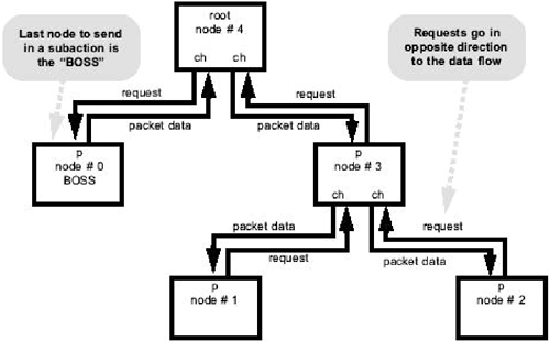
As indicated earlier, the FireWire protocol is efficient when these subaction gaps are relatively short compared with the packet length. On the other hand, the gap should be long enough to cover the round trip transmission delay of the longest connection. Therefore, the goal of longer reach and higher throughput demands a new arbitration mechanism to realize the benefit of faster physical layers. In 1394b, requests to transmit are delivered through short symbols while the current transmission is still in progress by taking advantage of full-duplex communication links. The permission to transmit is granted also through a short symbol by the BOSS (Bus Owner/Supervisor/Selector) node that just finished transmission. The subaction gap is therefore totally avoided between subsequent packets. To achieve reliable transmission on a single pair for the full-duplex transmission with no STROBE signal, scrambling and 8B10B encoding techniques are applied to data packets and control symbols. These scrambling and encoding techniques are commonly defined for all media. Detailed procedures are also defined to make 1394b transceivers backward-compatible with these original 1394 nodes. 8.3.2 1394b ArbitrationWhen transmission rates extend into the gigabit per second range and interconnect distances approach 100 m, the bus efficiency attainable with the subaction gap based arbitration mechanism becomes unacceptably low. The new specification improves the bus efficiency by taking advantage of the full-duplex nature of Beta mode signaling to implement a new BOSS arbitration method. In BOSS operation, arbitration request signaling is overlapped with data transmission on the full-duplex bus, and both isochronous and asynchronous requests may be pipelined for servicing in the succeeding isochronous or asynchronous intervals, respectively. Figure 8.24 illustrates the general concept of BOSS operation and shows how arbitration signaling is overlapped with data transmission on the full-duplex bus. Figure 8.24. BOSS Arbitration (From IEEE Std. 1394B-2002. Copyright © 2001 IEEE. All rights reserved.)
The FireWire node that is the last to transmit packet data in a subaction becomes the BOSS and is responsible for making the next arbitration decision. During packet transmission, the originator is the only one in the bus that can receive arbitration requests on every active port and is, therefore, in the best position to observe arbitration requests and to decide which port gets the bus next. In the BOSS arbitration mode, the start of the isochronous interval is marked by a CYCLE_START_EVEN/CYCLE_START_ODD control symbol transmitted by the cycle master and the gap between isochronous and asynchronous intervals is replaced by an ASYNC_EVEN/ASYNC_ODD control symbol sent by the BOSS that finished the last isochronous packet transmission. The purpose of alternating CYCLE_START_EVEN and CYCLE_START_ODD or ASYNC_EVEN and ASYNC_ODD symbols is to distinguish the current transmission interval from the next one. For example, a request for transmission of an asynchronous packet during the next transmission interval can be made by using the NEXT_ODD request symbol during an even interval. A control symbol consists of 4 bits. Bit combinations are 0001, 0010, 1101, and 1110 for CYCLE_START_EVEN, CYCLE_START_ODD, ASYNC_EVEN, and ASYNC_ODD, respectively. We also have bit combinations of 1000, 1011, 1010 (or 1001), and 0101 for GRANT, GRANT_ISOCH, DATA_PREFIX, and DATA_END as control symbols, respectively. The choice of 1010 or 1001 for DATA_PREFIX depends on whether the running bias is larger or smaller than 0. A request-to-transmit symbol consists of an isochronous request part of 3 bits and an asynchronous request part of 3 bits. Bit combinations are 001, 010, 100, 101, and 110 for CURRENT, NEXT_EVEN, NONE_ODD, NEXT_ODD, and NONE_EVEN asynchronous requests, respectively. Bit combinations are 00xx1, 01xx0, 10xx0, and 11xx0 for ISOCH_CURRENT, ISOCH_NONE, ISOCH_EVEN, and ISOCH_ODD isochronous requests, respectively. A request symbol of 8 bits is formed by concatenating an asynchronous request, as first 3 bits, and an isochronous request, as next 5 bits. Control and request symbols are scrambled before being transmitted over the media. A common scrambler with the following generator polynomial is used for control/request symbols as well as for data packets: Equation 8.6
These 4 bits of a control symbol are exclusive ORed with those 4 even bits of a group of 8 bits from the scrambler. A 4-bit scrambled control symbol is then encoded into a 10-bit character, named Cx for x = 0, 1, 2, . . . , 15, according to Table 8.2 for transmission over the media. Sometimes, the transmission of a control symbol is repeated to ensure proper propagation over connections with low transmission rates.
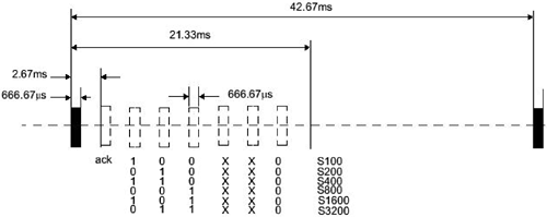
On the other hand, these 8 bits of a request symbol are exclusive ORed with a group of 8 bits from the scrambler. In addition, sixth and seventh bits of a scrambled request symbol are set to zeros. An 8-bit scrambled request symbol is encoded into a 10-bit character, named Dx.y for x = 0, 1, 2, . . . , 31, and y = 0, 1, 2, . . . , 7, according to these 8B10B rules, to be discussed shortly, for transmission over the media. Request symbols by themselves have no sender identifications. The BOSS node can receive only as many requests as the number of ports directly attached to it. The arbitration decision is therefore a distributed process involving intermediate nodes that pass the request with the highest priority among others in the direction toward the BOSS node. Priorities of isochronous and asynchronous requests are evaluated in their own respective phases and in consecutive cycles. EVEN and ODD phases are designed to allow a node to have a higher priority to transmit during the next cycle, while permitting others to have a chance to finish their transmission during the current cycle. Priorities for isochronous requests are 5, 4, 2, and 1 for ISOCH_CURRENT, ISOCH_ODD, ISOCH_EVEN, and ISOCH_NONE, respectively, in an ODD isochronous phase, and priorities of ISOCH_ODD and ISOCH_EVEN are reversed in an EVEN isochronous phase. In other words, a node sends an ISOCH_CURRENT request to transmit in the current cycle, an ISOCH_ODD or ISOCH_EVEN request (depending on if the current phase is EVEN or ODD) to transmit in the next cycle, and an ISOCH_NONE otherwise. Priorities for asynchronous requests are 5, 4, 3, 2, and 1 for NEXT_ODD, CURRENT, NONE_EVEN, NEXT_EVEN, and NONE_ODD, respectively, in an ASYNC_ODD phase, and priorities of NEXT_ODD and NEXT_EVEN and of NONE_ODD and NONE_EVEN are reversed in an ASYNC_EVEN phase. In other words, a node is sent a CURRENT request to transmit in the current cycle, a NEXT_ODD or NEXT_EVEN request (depending on if the current phase is ASYNC_EVEN or ASYNC_ODD) to transmit in the next cycle, and a NONE_EVEN or NONE_ODD otherwise. Requests from every node are presented to the current BOSS during every cycle. Priorities of requests from all nodes are evaluated before a particular request is relayed toward the BOSS. 8.3.3 1394b Initialization ProcessA 1394b port sends a tone with a frequency of between 48 and 61 MHz, an active duration of 666.67 µs, and a repetition period of 42.67 ms to detect if there is a 1394b port at the other side of a connection. If another 1394b port is detected by receiving a periodic tone of the specified active duration, a speed negotiation process between two 1394b ports with a sequence of tones during a period of 21.33 ms is then carried out as shown in Figure 8.25. The speed negotiation process is completed when the ack tone is received by both ports. Speed negotiations between pairs of ports are completed before the bus initialization of a 1394b network. Figure 8.25. BOSS Speed Signaling (From IEEE Std. 1394B-2002. Copyright © 2001 IEEE. All rights reserved.)
The 1394b bus initialization process is also carried out in bus initialization, tree identification, and self-identification phases. During the 1394b bus initialization phase, those nodes with only one active port are identified as leaves, and those nodes with more than one active port are identified as branches. Similarly, a node is elected as the root during the 1394b tree identification phase, and all active ports of other nodes are identified as either a parent or a child port depending on if their connected port is closer to the root. The election of a root begins by all leaf nodes sending a PARENT_NOTIFY request, 11000xx0, to their connected ports. Branch nodes that received PARENT_NOTIFY requests from leaf nodes send CHILD_NOTIFY requests, 01000xx0, as confirmations. Meanwhile, branch nodes send PARENT_NOTIFY requests through remaining ports. If a branch node receives a PARENT_NOTIFY request before sending out its own over the same port it confirms the child-parent relationship by acknowledging with a CHILD_NOTIFY request. The root contention process is used to resolve the situation when two branch nodes exchange their PARENT_NOTIFY requests. During the 1394b self-identification phase, each node selects a unique ID number and sends one to three short self-identification packets over the serial bus to any management entity. 8.3.4 1394b Packet TransmissionsPackets are transmitted over 1394b connections with additions of a packet prefix and a packet end at the beginning and end of a packet, respectively, as shown in Figure 8.26. Figure 8.26. 1394b Packet Transmission
The packet prefix consists of a speed code portion and a DATA_PREFIX symbol. The speed code portion can have more than one speed control symbol of SPEEDa (0100), SPEEDb (0111), or SPEEDc (1100). The packet itself is first scrambled using a sequence generated according to the generator polynomial of G(x) = x11 + x9 + 1 and then encoded according to these rules of 8B10B encoding. The 8B10B encoding is implemented by combining results of a 5B6B encoding, as shown in Table 8.3, and a 3B4B encoding, as shown in Table 8.4. "rd" is the running bias of the encoder. Either P7 or A7 is used depending on certain conditions. In other words, the first 5 bits of every byte of a packet are coded into 6 bits, and the next 3 bits are coded into 4 bits. These 6- and 4-bit outputs are combined to obtain the 10-bit 8B10B encoding result. Some padding of SPEEDc symbols might be necessary if a connection speed is faster than that of the original packet. The packet end consists of a stream of packet end symbols including DATA_END, DATA_PREFIX, GRANT, or GRANT_ISOCH.
| |||||||||||||||||||||||||||||||||||||||||||||||||||||||||||||||||||||||||||||||||||||||||||||||||||||||||||||||||||||||||||||||||||||||||||||||||||||||||||||||||||||||||||||||||||||||||||||||||||||||||||||||||||||||||||||||||||||||||||||||||||||||||||||||||||||||||||||||||||||||||||||||||||||||||||||||||||||||||||||||||||||||||||
EAN: 2147483647
Pages: 97

