8.4 1394b Twisted Cable Physical Layer Attributes
8.4.1 Shielded Twisted CableTo distinguish 1394b ports from those of traditional FireWire, a new connector with reversed contact orientations as shown in Figure 8.27 has been defined. The plug, as shown on the left side of the figure, has contacts on top and beneath bottom sides of an almost rectangular post in contrast with those inside a cavity. Correspondingly, contacts are inside the cavity of the new 1394b socket as indicated on the right side of the figure. Nine contacts are defined with two additional pins, 5 and 9, for connecting shields of these two twisted pairs and one additional pin, pin 7, which has been reserved for future use. Pins 6 and 8 are used for power supply, pins 1 and 2 belong to one shielded twisted pair, and pins 3 and 4 belong to the other pair. Some FireWire ports can operate in either traditional or 1394b modes. A cable with a traditional plug at one end and a new plug at the other end can be used to connect a traditional FireWire port and a bilingual port. A key, as shown at the bottom side of the plug and the socket, is designed to separate a 1394b-only port from a bilingual port. The key on a bilingual port, both plug and socket, is a little narrower than that of a 1394b-only port. Therefore, a 1394b-only plug can be inserted in both 1394b-only and bilingual ports while a bilingual plug will not fit a 1394b-only socket. Figure 8.27. Beta and Bilingual Connectors (From IEEE Std. 1394B-2002. Copyright © 2001 IEEE. All rights reserved.)
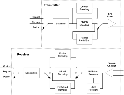
To accommodate higher rates, two new 1394b short cables have been defined along with these new connectors. These two new 1394b cables still consist of two shielded twisted signal pairs and one pair of power wires. The stranded copper wire of twisted signal pairs for the 4.5-m version of new cable is 25 AWG and associated power stranded copper wire is 22 AWG. Each stranded copper wire still consists of seven conductors. These conductors are 33 AWG for twisted pairs and 30 AWG for power wires, respectively. The stranded copper wire of these twisted pairs for the 2-m version of new cable is 30 AWG and the associated power stranded copper wire is 26 AWG. Each stranded copper wire also consists of seven conductors. These conductors are 38 AWG for twisted signal pairs and 34 AWG for power wires. Figure 8.28 shows some physical layer functional blocks of a 1394b transceiver. An arbitration function, external to these blocks, is necessary to make this transceiver participate in a 1394b serial bus. Depending on whether the input to the transmitter block is a control symbol, a request, or a packet, the corresponding encoding function is applied, and the prefix/end might be attached before the scrambled bits can reach the line driver. After the signal is amplified, the clock is recovered from the received signal to drive the bit pattern recovery block. Output from the recovery block is directed to the proper decoding function with prefix/end removed, if it is a packet, before it can reach the descrambler. Figure 8.28. 1394b Short Cable Transceiver Block Diagram
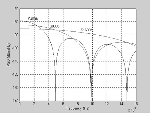
The maximum voltage level delivered by a line driver over a 1394b shielded twisted pair is 800 mV for baud rates of about 491, 983, and 1966 MHz corresponding to data rates of S400b, S800b, and S1600b* respectively, where b denotes the Beta mode. The 20% overhead for these higher baud rates is due to the 8B10B encoding. Power spectrum densities for 1394b at these baud rates can be calculated according to Equation 8.7
where T is the period of baud rate. PSDs for S400b, S800b, and S1600b are shown in Figure 8.29 with u = 0.8 V and R = 110 ohms. Figure 8.29. 1394b Power Spectrum Densities
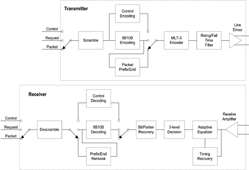
8.4.2 CAT 5 Unshielded Twisted Pair CableReplacing the line driver and the receiver amplifier of those used for 1394b shielded twisted pair with a combination of a MLT-3 encoder, a transmit filter, and a line driver for unshielded twisted pair and another combination of a corresponding receiver amplifier, an adaptive channel equalizer, a timing recovery circuit, and a 3-level decoder, the 1394b signal can be carried over Category 5 twisted pair cable at a maximum distance of 100 m as shown in Figure 8.30. Detailed requirements of MLT-3 transmission and reception can be found in ANSI X3.263-1995 standards document. Implementation and transmission performance of this MLT-3 line code based transceiver are similar to those of 100BaseTX. These new 1394b 8B10B encoding and arbitration techniques have made the choice of the transmission media relatively independent to the rest of transceiver design. Figure 8.30. 1394b CAT5 Transceiver Block Diagram
The same RJ45 connector is also used for the Category 5 twisted pair cable based 1394b transmission system. However, twisted pairs connected to pins 1/2 and to pins 7/8 are used to distinguish 1394b signals from those of 100BaseTX. The line voltage level of ±1 V and rising/falling time of 4 ns as defined for 100BaseTX are also adapted. Consequently, the corresponding PSD should be the same as that of 100BaseTX. This is also based on assumptions that the use of 8B10B instead of 4B5B encoding and the order of scrambling and encoding do not affect PSD. |
EAN: 2147483647
Pages: 97


