5.4 Channel Impulse Response Model
| We have examined the general transmission characteristics of indoor radio frequency channels in terms of signal losses. To utilize the transmission potential of the channel fully, an optimized transceiver architecture is required. The choice and design of the transceiver architecture including signal modulation and detection methods depend on the impulse response and the noise environment of the channel. The impulse response of an indoor radio frequency channel is useful at determining how fast the signaling rate could be with or without using certain types of channel equalization techniques. The channel impulse response can be exactly calculated if the reflection mechanism is relatively simple. Such a simple channel impulse response is the combination of the direct received signal and a limited number of reflections from a few walls. However, measurements show that the reflection mechanism of an indoor radio channel usually is more complicated because of reflections from walls and many other household objects. Therefore, the statistical modeling approach has been taken for the indoor radio environment. The statistical indoor radio channel model is based on extensive measurements of indoor radio environment at different locations. Through data analysis, statistical parameters have been derived depending on separation distance and whether the radio wave is directly received. We call the directly received case line of sight (LOS) and the indirectly received case obstructed (OBS). The measurement of the indoor radio channel can be carried out in the time domain or in the frequency domain. To measure the indoor radio channel impulse response in the time domain, we need to send a short time duration pulse (simulating an impulse) at one point and synchronously receive the pulse at another point. To represent the channel accurately, the sampling rate needs to be fast (at least twice the interested bandwidth). At gigahertz frequency bands, the direct sampling of the radio frequency channel at a high enough resolution presents a challenge to existing measurement equipment. In practice, the measurement of the indoor radio frequency channel is usually carried out in the frequency domain. The channel attenuation at each frequency is measured step by step to cover the whole spectrum. The time domain information is obtained through offline Fourier transforms. The step frequency should be chosen such that the Fourier-transform time domain response is long enough to cover all possible reflections. For example, a 1-MHz step frequency results in a time domain duration of 1 microsecond (µs). Since only the power attenuation level is measured, the Fourier-transform time domain information represents the squared magnitudes along with different time delays. The amplitude of the impulse response can be obtained by taking the square root. However, the phase information is still missing. This is the shortcoming of the frequency measurement method. A method of random phase has been used to supplement the information gathered from these Fourier-transform measurements when a complete channel impulse response is desired. The general indoor radio frequency channel impulse response has the format [4, 5] Equation 5.30
where ak is the amplitude at kth delay time, qk is the corresponding phase, and d(t - tk) is the delta function marking that particular delay instant. The statistical indoor radio frequency channel model gives detailed information for the sequence of aks based on separation distance and whether the signal is directly received. There are four statistical characteristics for the channel impulse response model. First, the amplitude is separation distance dependent. The amplitude is related to the separation distance as measured in terms of wavelength. Second, the amplitude is also delay sensitive. In general, the longer the delay, the smaller the amplitude. Specifically, the average amplitude at consecutive delay instances of the impulse response channel model is expressed as Equation 5.31
where Equation 5.32
For the OBS case, we have the following relationships: Equation 5.33
Third, the amplitude at each delay instance is a Gaussian random variable with the average amplitude as the mean and a standard deviation of 4 or 5 dB for LOS and OBS cases, respectively. Last, the occurrence of reflections at subsequent delay instances is a random variable with certain probabilities according to delay times. Specifically, for the LOS case, we have the following occurrence probabilities: Equation 5.34
For the OBS case, we have the following relationships: Equation 5.35
In summary, amplitudes of the indoor radio frequency channel impulse response model are Gaussian random variables as described by the following expression when reflections at particular delay instances exist: Equation 5.36
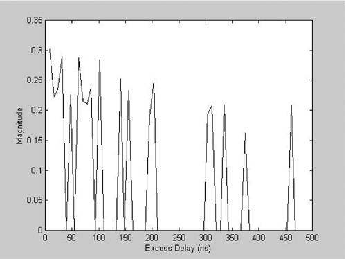
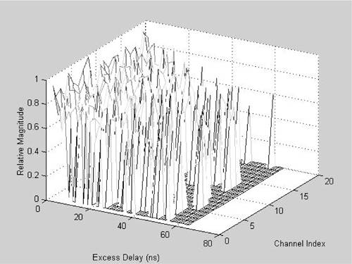
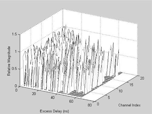
Measurements also indicate that delay spread is associated with individual reflections. In other words, the impulse response consists of a number of reflections that are disbursed in the time domain because of different channel distortions. Therefore, the resolution for the number of reflections is deterministic after the sampling rate has exceeded a certain threshold. According to studies, a time resolution of 7.8 ns has been used to generate LOS and OBS impulse response models as shown in Figures 5.13 and 5.14, respectively. Figures 5.15 and 5.16 show multiple LOS and OBS impulse response channel models in a three-dimensional arrangement. Figure 5.13. LOS Impulse Response
Figure 5.14. OBS Impulse Response
Figure 5.15. LOS Impulse Responses
Figure 5.16. OBS Impulse Responses
When a signal is transmitted over a particular radio frequency band, a modulation process is used to bring a baseband signal with a relatively narrow bandwidth to that particular radio frequency band. In the receiver, a reverse process called demodulation is used to get back the baseband signal. Figure 5.17 shows the block diagram of an indoor radio transmission system with modulation and demodulation processes. The modulation is usually carried out by combining the transmit shaping filtering and carrier frequency multiplication. The demodulation process is the combination of carrier frequency multiplication and low-pass filtering. Very often, the transmit shaping filter and the low-pass receiver filter have the same frequency response. For optimal signal detection efficiency, the combined frequency response of these filters resembles a raised cosine filter. Figure 5.17. Block Diagram of an Indoor RF System
The following analysis provides equivalent indoor radio frequency channel impulse response for a transmission system with modulation and demodulation process. For a transmission system with modulation and demodulation processes, two independent transmission channels can be realized by using cosine and sine phases of a carrier frequency. We call the first independent one an in-phase channel when the carrier frequency is multiplied with the cosine phase. We call the other independent one a quadrature channel when the sine phase of the carrier frequency is used in the multiplication. The baseband equivalent indoor radio frequency channel is analyzed first for the in-phase channel. The transmission system with shaping filtering, carrier multiplication, transmission over the channel, carrier frequency multiplication at the receiver, and low-pass filter can be described by Equation 5.37
where In particular, the transmit-shaping filtering process is described by Equation 5.38
Then the modulation process, a combination of the shaping and the carrier frequency multiplication, is described by Equation 5.39
After going through the channel, the signal is described by Equation 5.40
The signal after the receiver carrier frequency multiplication is described by Equation 5.41
After the whole demodulation process, including receiver low-pass filtering, the signal is represented by Equation 5.42
Multiplying the carrier frequency twice results in a baseband signal as well as a component with twice the carrier frequency. The amplitude of the baseband signal is slightly modified by the delay phase of the indoor radio frequency channel impulse response. The frequency shifting and amplitude modification effects can be described by Equation 5.43
Because of the low-pass nature of the filter f(t), the filtering process will eliminate the high-frequency term coswc(2t - i Equation 5.44
where Equation 5.45
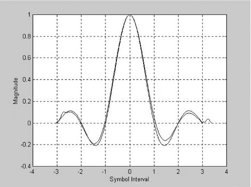
It can be shown that the same equivalent channel response exists for the quadrature channel. Figure 5.18 shows the received signal pulse using a raised cosine frequency response for the transmit and receiver filter pair and a signaling baud rate of 1 MHz over the 2.4-GHz indoor radio frequency channel. Figure 5.18. Baseband Channel Response with 1-MHz Baud Rate
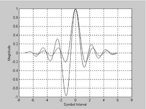
The distortion to the signal represented by this raised cosine pulse at a baud rate of 1 MHz is relatively small. The differences at baud sampling points of 1 T, 2 T, and so on indicate the magnitude of distortions. Because of the random nature of the indoor radio frequency channel, some pulse responses might be a little worse than this example. After observations at many random instances, it is concluded that a transceiver can be constructed without the use of a channel equalizer at this baud rate. Figure 5.19 shows the received signal pulse for a signaling baud rate of 2 MHz over the same 2.4-GHz indoor radio frequency channel. Figure 5.19. Baseband Channel Response with 2-MHz Baud Rate
This example shows that the use of an adaptive channel equalizer is necessary at a baud rate of 2 MHz. Otherwise, the negative peak before the main one will seriously affect the performance of a receiver. To make an adaptive channel equalizer work effectively under the rapidly changing radio frequency environment, some training sequence along with the random data information must be sent from the transmitter to the receiver. These training sequences become an overhead on the data and could reduce the net transmission throughput of the radio frequency channel. The optimal baud rate with or without the use of an adaptive channel equalizer can be found by performing experiments with this indoor radio frequency impulse response channel model. Most current indoor radio frequency transmission system signals at, around, or below 1 MHz to avoid using an adaptive channel equalizer. |

 ). We then have
EAN: 2147483647
Pages: 97