| BackboneFast is another Cisco enhancement designed to complement UplinkFast. UplinkFast is designed to detect direct failures, whereas BackboneFast is designed to detect indirect failures. An indirect failure is not immediately detected when it occurs, and under normal STP operation, the Max Age timer is used to detect an indirect failure by defining the maximum amount of time that must pass before the root bridge is considered down due to configuration BPDUs not being received from the root. By default, the Max Age timer is configured as 20 seconds, which means that it takes STP 20 seconds just to detect an indirect failure. After an indirect failure has been detected (i.e., the Max Age timer expires), the Listening and Learning phases (by default, a total of 30 seconds) are transitioned through until a Forwarding or Blocking state is reached for each port. This means that by default, an indirect failure requires 50 seconds to converge to a new topology that is actively forwarding user data. BackboneFast effectively eliminates the Max Age timeout period associated with an indirect failure, lowering convergence from the default 50 seconds to 30 seconds. Note that it does not eliminate the Listening and Learning periods (30 seconds) like UplinkFast does. BackboneFast should be enabled on every switch in your network (unlike UplinkFast). This recommendation comes because BackboneFast is a mechanism that detects a possible indirect failure and then queries the network to verify that an indirect failure has occurred. BackboneFast works on the assumption that if the designated bridge (and only the designated bridge) for a segment suddenly starts sending inferior BPDUs (i.e., root bridge ID is higher than current root bridge ID), then it is likely that an indirect failure has occurred. If the inferior BPDUs are being received from a non-designated bridge, then they are ignored because they indicate a failure further downstream in the topology and no action is required on any bridges upstream from the failure. If the inferior BPDUs are being received from the designated bridge, and no blocked ports exist on the switch (only one path to the root), then the switch immediately expires the Max Age timer because it knows it only has one path to the root bridge. If the switch does have blocked ports, the process gets more complicated. The switch then sends root link query (RLQ) requests out all non-designated ports (except the port that received the inferior BPDU). An RLQ request is a Cisco-proprietary frame that is sent by a switch to query upstream switches if their (the upstream switch's) connection to the root bridge is stable. Each RLQ request is answered by an RLQ response that indicates that the path to the root is stable. Each switch that receives the RLQ request answers immediately if it is the root bridge or it knows that the root bridge connection has been lost. If neither of these conditions is the case, the switch propagates the RLQ request out the local root port, with this process continuing until the root bridge status is known. This method of propagating RLQ requests out the root ports of upstream switches ensures the RLQ request eventually reaches the root bridge or a switch that knows the root bridge is down. NOTE Because the RLQ mechanism is Cisco-proprietary, you must ensure that all switches in the network are Cisco switches and that BackboneFast is supported and enabled on each. If a Cisco switch does not have BackboneFast enabled, it ignores RLQ messages, which breaks the BackboneFast mechanism.
Once the RLQ request eventually reaches the root bridge (or a switch that knows the root bridge is down), because that switch is the root bridge, it generates an RLQ response, which is propagated in an identical manner to configuration BPDUs until the response reaches the requesting switch. If on the original switch that generated the RLQ request the RLQ response is not received on the root port, then the switch knows it has lost its connection to the root bridge and immediately expires its Max Age timer. Figure 4-30 shows the topology used to demonstrate BackboneFast for this scenario. Figure 4-30. BackboneFast 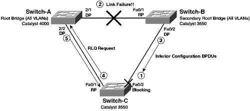
The following steps describe the events that occur in Figure 4-30: Step 1. | The network has converged to a stable STP topology, and interface Fa0/2 on Switch-C is in a blocking state, because Switch-B has a lower sender bridge ID than Switch-C. (Switch-B is the secondary root bridge.)
| Step 2. | A failure occurs on the link between Switch-A and Switch-B. Because the path to the root bridge (i.e., the root port) on Switch-B has gone down (interface Fa0/1), Switch-B immediately assumes that it is the new root bridge and starts sending configuration BPDUs out interface Fa0/2 listing Switch-B as the root.
| Step 3. | The new configuration BPDUs are received by Switch-C (remember BPDUs are sent and received on blocking ports), with Switch-B listed as the root bridge. Because Switch-C is still receiving BPDUs from Switch-A, the BPDUs received on interface Fa0/2 are considered inferior.
| Step 4. | Under normal STP operation, Switch-C ignores inferior BPDUs until the Max Age timer expires on the interface. At this point, assuming Switch-C is still receiving superior configuration BPDUs via its root port, Switch-C then starts sending the superior configuration BPDUs out interface Fa0/2, and the interface transitions through the Listening and Learning phases until a Forwarding state is reached. The total convergence of this process takes 50 seconds by default (Max Age of 20 seconds + 2 * Forward Delay of 15 seconds).
| Step 5. | Because BackboneFast is enabled on Switch-C, Switch-C reacts differently to the inferior configuration BPDU being received. The inferior configuration BPDU is received from the previously designated bridge for the segment (Switch-B), which indicates to Switch-C that Switch-B has lost its connection to the root bridge. The inferior configuration BPDUs could also indicate that Switch-C might have lost its connection to the root, so Switch-A generates an RLQ request frame that is sent out all non-designated (upstream) ports (i.e., blocked ports and root ports). The RLQ requests are not sent out designated ports, because these only lead to downstream switches and the root is always upstream. In Figure 4-30 then, a RLQ response is sent out interface Fa0/1 to Switch-A.
| Step 6. | Because Switch-A is the root bridge (and has BackboneFast enabled), it sends an RLQ response back to Switch-C. This response indicates to Switch-C that it still has a connection to the root bridge. Because Switch-C has a connection to the root bridge, it needs to expire only the Max Age timer on interface Fa0/2, not the Max Age timer on interface Fa0/1. If the RLQ response were received on another non-designated port, this would indicate that Switch-C had lost its connection to the root, and the Max Age timer would be immediately expired on the root port (Fa0/1).
|
Interface Fa0/2 still goes through the Listening and Learning phases because it may be found that Switch-B is still the designated bridge for the segment between Switch-B and Switch-C. Because the Max Age timer has been expired prematurely, convergence has been reduced from 50 seconds to 30 seconds, using the default STP timers. If the failure had also affected connectivity to the root bridge for Switch-C, the RLQ mechanism would have allowed Switch-C to also expire the Max Age timer prematurely for the root port. NOTE Remember, BackboneFast is designed to detect indirect failures only, and reduces only the Max Age timeout period. The Listening and Learning phases must still be transitioned through, as loops in the new topology must still be detected.
Enabling BackboneFast Because of the proprietary RLQ Query/Response mechanism, BackboneFast needs to be enabled on all switches in the Layer 2 network, and all switches must be Cisco switches that support the feature. NOTE This scenario uses the topology of Figure 4-30, assumes that a single VLAN (VLAN 1) is in use and that Switch-A has been configured as the root bridge, with Switch-B configured as the secondary root bridge. All other spanning-tree parameters are configured as the default on all switches.
On CatOS, BackboneFast is disabled by default and can be enabled or disabled globally for the entire switch. To enable BackboneFast on a CatOS switch, use the following command: set spantree backbonefast enable
You can verify BackboneFast is enabled by using the show spantree backbonefast command. On Cisco IOS, BackboneFast is disabled by default and can be enabled or disabled globally for the entire switch. To enable BackboneFast on a Cisco IOS switch, use the following global configuration command: spanning-tree backbonefast
In the topology of Figure 4-30, to reduce the convergence time associated with indirect failures in the network, you can enable BackboneFast, which eliminates the Max Age timer from the total convergence time required for an indirect failure. To enable BackboneFast, you must enable the feature on all switches. Example 4-57 through Example 4-59 demonstrates configuring BackboneFast on all switches in Figure 4-57. Example 4-57. Configuring BackboneFast on Switch-A Switch-A> (enable) set spantree backbonefast enable Backbonefast enabled for all VLANs
Example 4-58. Configuring BackboneFast on Switch-B Switch-B# configure terminal Switch-B(config)# spanning-tree backbonefast
Example 4-59. Configuring BackboneFast on Switch-C Switch-C# configure terminal Switch-C(config)# spanning-tree backbonefast
Example 4-60 demonstrates verifying BackboneFast is configured on Switch-A (CatOS). Example 4-60. Verifying BackboneFast on Switch-A Switch-A> (enable) show spantree backbonefast Backbonefast is enabled.
Example 4-61 demonstrates verifying BackboneFast is configured on Switch-B (Cisco IOS). Example 4-61. Verifying BackboneFast on Switch-B Switch-B# show spanning-tree summary Root bridge for: none. Extended system ID is enabled. PortFast BPDU Guard is disabled EtherChannel misconfiguration guard is enabled UplinkFast is disabled BackboneFast is enabled Default pathcost method used is short Name Blocking Listening Learning Forwarding STP Active ---------------------- -------- --------- -------- ---------- ---------- VLAN0001 0 0 0 3 3 ---------------------- -------- --------- -------- ---------- ---------- 1 vlans 0 0 0 3 3 BackboneFast statistics ----------------------- Number of transition via backboneFast (all VLANs) : 0 Number of inferior BPDUs received (all VLANs) : 0 Number of RLQ request PDUs received (all VLANs) : 0 Number of RLQ response PDUs received (all VLANs) : 0 Number of RLQ request PDUs sent (all VLANs) : 0 Number of RLQ response PDUs sent (all VLANs) : 0
In Example 4-61, you can see that BackboneFast is enabled and can also see statistics for BackboneFast. Notice that the show spanning-tree summary command on Cisco IOS can also be used to determine if other spanning tree enhancements, such as UplinkFast and BPDU Guard, are enabled. NOTE You can use show spanning-tree backbonefast command to just view the BackboneFast information shown in Example 4-61.
Testing BackboneFast To test BackboneFast, you enable the debugging of spanning-tree Backbonefast events on Switch-C and simulate an indirect failure between Switch-A and Switch-B by shutting interface Fa0/1 on Switch-B. You should be able to see that the Max Age timer is expired prematurely and that interface Fa0/2 on Switch-C moves to a Forwarding state after 30 seconds, as opposed to the normal 50 seconds. Step 1. | On all switches in the network, ensure that BackboneFast is disabled. Examples 4-62 through 4-64 show the configuration required to disable BackboneFast on all switches.
Example 4-62. Disabling BackboneFast on Switch-A Switch-A> (enable) set spantree backbonefast disable Backbonefast disabled for all VLANs
Example 4-63. Disabling BackboneFast on Switch-B Switch-B# configure terminal Switch-B(config)# no spanning-tree backbonefast
Example 4-64. Disabling BackboneFast on Switch-C Switch-C# configure terminal Switch-C(config)# no spanning-tree backbonefast
| Step 2. | On Switch-C, ensure that logging of debug messages is enabled to the console and then enable the debugging of STP events, as shown in Example 4-65.
Example 4-65. Debugging Spanning Tree BackboneFast Events on Switch-C Switch-C# configure terminal Switch-C(config)# logging console debugging Switch-C(config)# exit Switch-C# debug spanning-tree events Spanning Tree event debugging is on
| Step 3. | To simulate an indirect failure with regards to Switch-C, shut down the interface on Switch-B (interface Fa0/1) that is attached to Switch-A, as shown in Example 4-66.
Example 4-66. Shutting Down an Interface on Switch-B Switch-B# configure terminal Switch-B(config)# interface fa0/1 Switch-B(config-if)# shutdown
| Step 4. | On Switch-C, you see the following debugging output, as shown in Example 4-67.
Example 4-67. Debug Output on Switch-C after an Indirect Failure Switch-C# 00:34:06: STP: VLAN0001 heard root 28673-0009.b7aa.9c80 on Fa0/1 00:34:07: STP: VLAN0001 heard root 28673-0009.b7aa.9c80 on Fa0/1 00:34:08: STP: VLAN0001 heard root 28673-0009.b7aa.9c80 on Fa0/2 00:34:09: STP: VLAN0001 heard root 28673-0009.b7aa.9c80 on Fa0/2 00:34:10: STP: VLAN0001 heard root 28673-0009.b7aa.9c80 on Fa0/2 00:34:11: STP: VLAN0001 heard root 28673-0009.b7aa.9c80 on Fa0/2 00:34:12: STP: VLAN0001 heard root 28673-0009.b7aa.9c80 on Fa0/2 00:34:13: STP: VLAN0001 heard root 28673-0009.b7aa.9c80 on Fa0/2 00:34:14: STP: VLAN0001 heard root 28673-0009.b7aa.9c80 on Fa0/2 00:34:15: STP: VLAN0001 heard root 28673-0009.b7aa.9c80 on Fa0/2 00:34:16: STP: VLAN0001 heard root 28673-0009.b7aa.9c80 on Fa0/2 00:34:17: STP: VLAN0001 heard root 28673-0009.b7aa.9c80 on Fa0/2 00:34:18: STP: VLAN0001 heard root 28673-0009.b7aa.9c80 on Fa0/2 00:34:19: STP: VLAN0001 heard root 28673-0009.b7aa.9c80 on Fa0/2 00:34:20: STP: VLAN0001 heard root 28673-0009.b7aa.9c80 on Fa0/2 00:34:21: STP: VLAN0001 heard root 28673-0009.b7aa.9c80 on Fa0/2 00:34:22: STP: VLAN0001 heard root 28673-0009.b7aa.9c80 on Fa0/2 00:34:23: STP: VLAN0001 heard root 28673-0009.b7aa.9c80 on Fa0/2 00:34:24: STP: VLAN0001 heard root 28673-0009.b7aa.9c80 on Fa0/2 00:34:24: STP: VLAN0001 Fa0/2 -> listening 00:34:25: STP: VLAN0001 Topology Change rcvd on Fa0/2 00:34:25: STP: VLAN0001 sent Topology Change Notice on Fa0/1 00:34:26: STP: VLAN0001 Topology Change rcvd on Fa0/2 00:34:26: STP: VLAN0001 sent Topology Change Notice on Fa0/1 00:34:39: STP: VLAN0001 Fa0/2 -> learning 00:34:54: STP: VLAN0001 sent Topology Change Notice on Fa0/1 00:34:54: STP: VLAN0001 Fa0/2 -> forwarding
In Example 4-67, notice that from 00:34:06 to 00:34:24 (approximate 20 seconds or the Max Age timer), Switch-C hears inferior configuration BPDUs on interface Fa0/2, due to the root port on Switch-B going down. Switch-C ignores these; however, after not hearing the correct configuration BPDUs on interface Fa0/2 for the Max Age time (20 seconds), interface Fa0/2 is placed into a Listening state (00:34:24). Interface fa0/2 then transitions to a Learning state and, finally, into a Forwarding state, as it has become the designated port for the segment between Switch-C and Switch-B. Notice that the time between when the indirect failure actually occurred (approximately 00:34:06) and when interface Fa0/2 moved into a Forwarding state (at 00:34:54) is approximately 50 seconds, which is the expected convergence time for an indirect failure under normal STP operation.
| Step 5. | On all switches in the network, enable BackboneFast. Also re-enable interface Fa0/1 on Switch-B. Examples 4-68 through 4-70 show the configuration required to enable BackboneFast on all switches.
Example 4-68. Enabling BackboneFast on Switch-A Switch-A> (enable) set spantree backbonefast enable Backbonefast enabled for all VLANs
Example 4-69. Enabling BackboneFast on Switch-B Switch-B# configure terminal Switch-B(config)# spanning-tree backbonefast Switch-B(config)# interface fa0/1 Switch-B(config-if)# no shutdown
Example 4-70. Enabling BackboneFast on Switch-C Switch-C# configure terminal Switch-C(config)# spanning-tree backbonefast
| Step 6. | On Switch-C, verify that interface Fa0/2 is now blocking again. Ensure that the debugging of spanning-tree events is enabled and also enable the debugging of BackboneFast events, as shown in Example 4-71.
Example 4-71. Debugging Spanning Tree BackboneFast Events on Switch-C Switch-C# show spanning-tree blockedports Name Blocked Interfaces List -------------------- ------------------------------------ VLAN0001 Fa0/2 Number of blocked ports (segments) in the system : 1 Switch-C# show debugging Spanning Tree: Spanning Tree event debugging is on Switch-C# debug spanning-tree backbonefast Spanning Tree backbonefast general debugging is on
In Example 4-71, you can see that interface Fa0/2 is blocking once again because the link between Switch-A and Switch-B has been re-enabled. The show debugging output confirms that spanning-tree event debugging is already enabled.
| Step 7. | To simulate an indirect failure with regards to Switch-C, shut down the interface on Switch-B (interface Fa0/1) that is attached to Switch-A, as shown in Example 4-72.
Example 4-72. Shutting Down an Interface on Switch-B Switch-B# configure terminal Switch-B(config)# interface fa0/1 Switch-B(config-if)# shutdown
| Step 8. | On Switch-C, you should see the following debugging output, as shown in Example 4-73.
Example 4-73. Debug Output on Switch-C after an Indirect Failure with BackboneFast Enabled Switch-C# 00:58:17: STP: VLAN0001 heard root 28673-0009.b7aa.9c80 on Fa0/2 00:58:17: STP FAST: received inferior BPDU on VLAN0001 FastEthernet0/2. 00:58:17: STP FAST: sending RLQ request PDU on VLAN0001 FastEthernet0/1 00:58:17: STP FAST: Received RLQ response PDU on VLAN0001 FastEthernet0/1. 00:58:17: STP: VLAN0001 Fa0/2 -> listening 00:58:18: STP: VLAN0001 Topology Change rcvd on Fa0/2 00:58:18: STP: VLAN0001 sent Topology Change Notice on Fa0/1 00:58:19: STP: VLAN0001 Topology Change rcvd on Fa0/2 00:58:19: STP: VLAN0001 sent Topology Change Notice on Fa0/1 00:58:32: STP: VLAN0001 Fa0/2 -> learning 00:58:47: STP: VLAN0001 sent Topology Change Notice on Fa0/1 00:58:47: STP: VLAN0001 Fa0/2 -> forwarding
In Example 4-73, at 00:58:17 an inferior configuration BPDU is received from Switch-B on Fa0/2. The next three events are STP FAST events, which relate to BackboneFast operation. Notice that BackboneFast detects an inferior BPDU has been received, sends a RLQ request out interface Fa0/1 towards the root bridge (Switch-A), and receives an RLQ response (from Switch-A). Because Switch-C knows that the connection to the root is stable, it then immediately expires the Max Age timer on interface Fa0/2 and places the interface into a Listening state (still at 00:58:17). The interface is then transitioned into the Learning state (at 00:58:32) and then finally into a Forwarding state (at 00:58:47). Notice that the time between when the indirect failure actually occurred (approximately 00:58:17) and when interface Fa0/2 moved into a Forwarding state (at 00:58:47) is approximately 30 seconds, which indicates that by enabling BackboneFast, the Max Age timer is expired almost immediately after an indirect failure.
|
|