6.5 Routing Mechanisms
6.5 Routing Mechanisms
The routing mechanisms we will consider here are establishing routing flows, identifying and classifying routing boundaries, and manipulating routing flows.
6.5.1 Establishing Routing Flows
In preparation to discuss boundaries and route manipulation, we want to understand how flows will likely be routed through the network. As we will see in this chapter, addressing and routing are both closely coupled to the flow of routing information in the network, and the addressing and routing architecture is based partially on establishing these flows.
Determining routing flows begins with the flow analysis process. When you develop flows in the flow specification and flow map, they form the foundation for routing flows, as traffic flows are what are routed through the network.
The process of establishing routing flows in the network consists of segmenting the network into functional areas and workgroups, identifying boundaries between these areas, and then forming the relationships between boundaries and routing flows.
Functional areas (FA) are groups within the system that share a similar function. Groups may be of users (workgroups), applications, devices, or combinations of these, and they may share similar jobs/tasks, physical locations, or functions within the network (e.g., backbone routing). Workgroups (WG) are groups of users that have common locations, applications, and requirements, or that belong to the same organization.
The purpose of FAs is to simplify the routing architecture. They can cross physical boundaries, such as rooms, floors, and buildings. A WG is similar to an FA but is one level lower in hierarchy.
Consider Figure 6.12. In this figure, there are multiple WGs, in this case based on organizations within a company. FAs are created: the Scientists and Accounting groups in Building C, the two Management WGs in Building B, the Scientists groups across Buildings A and C, and the backbone between the buildings. Notice that FAs are connected with routers.
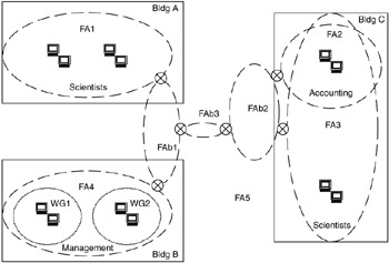
Figure 6.12: Example of workgroups and functional areas.
6.5.2 Identifying and Classifying Routing Boundaries
Routing boundaries are physical or logical separations of a network, based on requirements for or administration of that network.
Physical boundaries can be identified by isolation LANs or demilitarized zones (DMZs), physical interfaces on network equipment, or physical security. Logical boundaries can be identified by FAs, WGs, administrative domains, such as autonomous systems (AS), and routing management domains.
Autonomous systems have AS numbers associated with them. Routing management domains are often the same as ASs but can be either a subset or a superset of one or more ASs. Security domains are places where security devices are located and may use public address space outside the security boundary and private address space inside.
The type of routing protocol used to pass routing information across the boundary may also distinguish boundaries. Two general types of routing protocols exist. Exterior Gateway Protocols (EGPs) communicate routing information (reachability and metrics) primarily between ASs. Interior Gateway Protocols (IGPs) communicate routing information primarily within an AS. The word primarily is used here, for EGPs can be used within an AS and IGPs can be used between ASs, although this is rarely done. Later in this chapter we will look at ways to combine EGP and IGP use both within and between ASs.
Here, we use the term hard boundary to describe a routing boundary in which EGPs are predominantly used to pass routing information, whereas a soft boundary is a routing boundary in which IGPs are predominantly used. Hard boundaries are found between ASs, between an AS and an external network (which may or may not have an AS associated with it) or at well-defined separations between networks within an AS (e.g., at interfaces between internal organizations within a company in which different administrative domains exist). Hard boundaries are also found at interfaces to ISPs and are associated with DMZs. Figure 6.13 shows an example of a hard boundary.
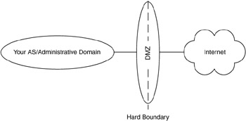
Figure 6.13: Example of a hard boundary.
In this example, a network is used to separate an enterprise AS from an ISP. A network that is used to separate other networks (provide a buffer between them) is often termed an isolation LAN (iLAN). Another term for iLAN is DMZ. DMZ denotes a buffer area between two factions—in this case, the two networks being separated. This is a common hard boundary and is one in which an EGP is likely to be used. Another example is when an enterprise wants to restrict communications between certain organizations within that enterprise (e.g., to/from the Accounting WG). Although the entire organization is within an AS, the boundary between the Accounting WG and the rest of the AS is similar to a DMZ (it could be considered an internal DMZ), so this is also a hard boundary. An EGP or IGP may be used in this case.
Soft boundaries are typically found within a single AS and are usually placed at the junction of FAs or WGs, as in Figure 6.14. In this figure, all of the interfaces between FAs are soft boundaries.
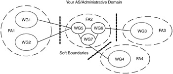
Figure 6.14: Example of a soft boundary.
Why are we interested in determining routing boundaries for our network? Routing boundaries are important because they are the focal points for routing flows. Recall from our examples that between FAs and between ASs, hard and soft boundaries are located at routers, which aggregate routing traffic. These are also locations where hierarchies are established in the network. Figure 6.15 shows boundaries and routing flows for a network.
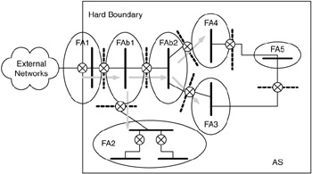
Figure 6.15: Boundaries and routing flows in a network.
Routing flows are flows of routing information, passed between FAs, as well as between ASs. This routing information includes routing initialization, updates, transients, and background traffic such as "hello" or "keepalive" messages. Routing boundaries and flows are important to the development of the architecture and design, for routing flows can be manipulated at routing boundaries.
6.5.3 Manipulating Routing Flows
Manipulating (i.e., controlling) routing flows within the network is vital to the proper operation and performance of the network. The right combination of addressing and routing is important in this process to localize routing flows whenever possible.
Several techniques can be used to manipulate routing flows at hard and soft boundaries. We can supply a default route through our network via default route propagation. We can use route filtering to hide routes, and route aggregation to simplify advertisements. We can develop peering relationships between networks or ASs across boundaries. We can also develop routing policies and policy enforcement.
A default route is the route used when there is no other route for that destination. Usually, this is the route with the highest available capacity to external networks. Default route propagation is the technique used to inform the network (or subnets or FAs) of the default path; propagation begins at the exit point for the network.
Route filtering is the technique of applying route filters to hide networks from the rest of an AS, or to add, delete, or modify routes in the routing table. A route filter is a statement, configured in one or more routers, that identifies one or more IP parameters (e.g., an IP source or destination address) and an action (e.g., drop or forward) to be taken when traffic matches these parameters. Route filtering is commonly used at hard boundaries. When the IGP OSPF is used, route filtering should not be used to hide networks internal to the OSPF network. This is due to the nature of the route-calculation algorithm in OSPF, which will be discussed later in this chapter.
Route aggregation is the technique of exchanging routing information between ASs, usually between service providers with transit networks and between large customer networks. This technique is typically used at hard boundaries and may include policy information. Historically, on the Internet, peering was the free and open exchange of routes between large transit networks, but changes in the structure and operation of the Internet have modified peering arrangements, so now they are somewhat competitive.
Policies are higher-level abstractions of the route filtering technique described earlier. Just as a route filter takes an action (e.g., drop, accept, modify) on traffic that matches one or more parameters (e.g., IP addresses), a policy takes a similar action on traffic that matches one or more AS parameters (e.g., AS number or list of AS numbers and metrics, time of day, cost).
Policies allow an AS to accept or deny traffic, or to modify routing information passed between ASs, based on high-level parameters. This allows decisions about routing traffic to be made on a basis other than route metrics. Policies are typically applied across hard boundaries and are currently used with the EGP BGPv4, discussed later in this chapter.
For example, consider a group of interconnected ASs, as in Figure 6.16. Router 1 peers with Routers 2 and 3. Routers 2 and 3 enforce a policy that traffic from AS1 must transit AS2 in order to get to AS4, and this traffic cannot transit AS3.
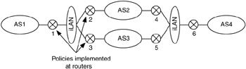
Figure 6.16: Policy enforcement between autonomous systems.
To illustrate these route-manipulation techniques, we will discuss each as applied to the example in Figure 6.17.
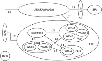
Figure 6.17: Example for route-manipulation techniques.
The routing requirements for AS1 are as follows:
| 1.1. | Provide primary Internet access for AS1 is through ISPa. |
| 1.2. | Provide redundant (secondary) Internet access for AS1 is through ISPb. |
| 1.3. | Allow AS2 traffic to transit (go through) AS1 to get redundant Internet access via ISPa. |
| 1.4. | Only allow communication between WGa1 in AS1 and WGc1 in AS2 via link L7. |
Requirements 1.1 and 1.2 are solved by establishing peering agreements with both ISPa and ISPb. This agreement specifies that ISPa should propagate a default route to AS1 with a lower routing cost than the default route from ISPb to AS1. Also, within this peering agreement, AS1 will advertise an aggregate route for its subnets to ISPa with a lower cost than to ISPb. Peering is done across a hard boundary, so it is typically accomplished with an EGP (e.g., BGP4).
For requirement 1.3, a third peering agreement is developed between AS1 and AS2 via links L1 and L2. AS1 accepts aggregate routes from AS2 and passes them through AS1 to ISPa at a higher cost than the cost AS2 uses to ISPb. The earlier peering agreement is modified to allow AS1 to send AS2's routes to it. ISPa agrees to propagate AS2's routes to Internet at higher cost than ISPb.
For requirement 1.4, a fourth peering agreement is established between AS1 and AS2 via link L7. AS1 accepts route advertisements from AS2/WGc1 for subnets within this WG via link L7. Route filtering is applied to block any other traffic.
The results of applying route-manipulation techniques to the routing requirements of AS1 are shown in Figure 6.18.

Figure 6.18: Results of route-manipulation techniques applied to AS1.
The routing requirements for AS2 are as follows:
| 2.1. | WGc5 can communicate with WGc4 only via link L8. |
| 2.2. | Only allow traffic from AS1 that is received over link L7 destined for WGc1 to pass; block all other traffic. |
| 2.3. | Allow FAc3 to use FAc4 as an alternative path to the Internet via link L6. |
| 2.4. | Do not allow FAc2 to use FAc3 as an alternative path to Internet via link L8. |
| 2.5. | Do not advertise WGc2. |
| 2.6. | WGc1 can communicate with AS1/WGa1 via only link L7; deny all other traffic. |
| 2.7 | All other FAs must use FAc1 as the default path. |
| 2.8. | Use AS1 as a transient AS for redundant access to the Internet via ISPa. |
| 2.9. | Use ISPb as primary access to Internet. |
Requirement 2.1 is solved by applying route filtering at both WGc5 and WGc4 to force this routing to take place and to prevent other WGs from using link L8. For 2.2, a peering agreement with AS1 is established, and route filtering is applied at link L7. Requirement 2.3 is solved by having FAc4 propagate a default route via link L6 to FAc3 with a higher cost than FAc3 is getting from FAc1. In 2.4, route filtering is applied to FAc2 and FAc3, as was done in problem 2.1.
For requirement 2.5, route filters are applied at routers that connect to WGc2 to keep that WG from being advertised. In requirement 2.6, route filtering is used again, this time to force communications via link L7. Be careful to not allow WGc1 to use link L7 as access to the Internet. In 2.7, FAc1 propagates the default route to all FAs. All FAs will aggregate route advertisements at the soft boundaries.
For requirement 2.8, another peering agreement (agreement number 5) is established with AS1 to allow AS2 to use AS1 as a transit AS to access ISPa in the event that ISPb fails. AS2 must advertise aggregate routes to AS1 with a higher cost than it is sending to ISPb.
In requirement 2.9, a peering agreement is established between ISPb and AS2. AS2 will advertise aggregate routes to ISPb, ISPb will advertise default to AS2, and ISPb will propagate AS2's routes to the Internet.
The results of applying route-manipulation techniques to the routing requirements of AS2 are shown in Figure 6.19.
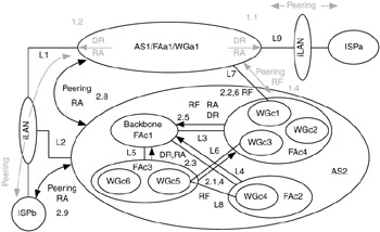
Figure 6.19: Results of route-manipulation techniques applied to AS2.
EAN: 2147483647
Pages: 161