Lesson 4: Token Ring
This lesson introduces the Token Ring network architecture. The Token Ring architecture was developed in the mid-1980s by IBM. It is the preferred method of networking by IBM and is therefore found primarily in large IBM mini- and mainframe installations. Even though the popularity of Ethernet has decreased the market share for Token Ring, it is still an important player in the network market. Token Ring specifications are governed by the IEEE 802.5 standards, which are covered in more detail in Chapter 5, "Introducing NetworkStandards." This lesson presents an overview of the major Token Ring components, features, and functions.
After this lesson, you will be able to:
- Describe the features of a Token Ring network.
- Identify the major components of a Token Ring network.
- Determine the components needed to implement a Token Ring network at a given site.
Estimated lesson time: 25 minutes
Overview
IBM's version of Token Ring was introduced in 1984 for the entire range of IBM computers and computing environments including:
- Personal computers.
- Midrange computers.
- Mainframe computers and the Systems Network Architecture (SNA) environment (SNA is IBM's networking architecture).
The goal of IBM's version of Token Ring was to facilitate a simple wiring structure using twisted-pair cable that connects a computer to the network through a wall socket, with the main wiring located in a centralized location.
In 1985, the IBM Token Ring became an American National Standards Institute (ANSI)/IEEE standard. (ANSI is an organization that was formed in 1918 for the development and adoption of trade and communication standards in the United States; ANSI is the American representative of ISO.)
Token Ring Features
A Token Ring network is an implementation of IEEE standard 802.5. Their token-passing ring access method, more than their physical cable layout, distinguishes Token Ring networks from other networks.
Architecture
The architecture of a typical Token Ring network begins with a physical ring. However, in its IBM implementation, a star-wired ring, computers on the network are connected to a central hub. Figure 3.23 shows a logical ring and a physical star topology. The logical ring represents the token's path between computers. The actual physical ring of cable is in the hub. Users are part of a ring, but they connect to it through a hub.
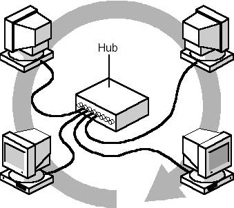
Figure 3.23 Logical ring, in which the physical ring is in the hub
Token Ring Basics
A Token Ring network includes the following features:
- Star-wired ring topology
- Token-passing access method
- Shielded and unshielded twisted-pair (IBM Types 1, 2, and 3) cabling
- Transfer rates of 4 and 16 Mbps
- Baseband transmission
- 802.5 specifications
Frame Formats
The basic format of a Token Ring data frame is shown in Figure 3.24 and described in Table 3.9 that follows. The sizes of the fields in Figure 3.24 are not representative of the sizes of the fields in an actual frame. The data field makes up the vast majority of the frame.

Figure 3.24 Token Ring data frame
Table 3.9 Components of a Token Ring Frame
| Frame field | Description |
|---|---|
| Start delimiter | Indicates start of the frame |
| Access control | Indicates the frame's priority and whether it is a token or a data frame |
| Frame control | Contains either Media Access Control information for all computers or "end station" information for only one computer |
| Destination address | Indicates the address of the computer to receive the frame |
| Source address | Indicates the computer that sent the frame |
| Information, or data | Contains the data being sent |
| Frame check sequence | Contains CRC error-checking information |
| End delimiter | Indicates the end of the frame |
| Frame status | Tells whether the frame was recognized, copied, or whether the destination address was available |
How Token Ring Networking Works
When the first Token Ring computer comes online, the network generates a token. The token is a predetermined formation of bits (a stream of data) that permits a computer to put data on the cables. The token travels around the ring polling each computer until one of the computers signals that it wants to transmit data and takes control of the token. A computer cannot transmit unless it has possession of the token; while the token is in use by a computer, no other computer can transmit data.
After the computer captures the token, it sends a data frame (such as the one shown in Figure 3.25) out on the network. The frame proceeds around the ring until it reaches the computer with the address that matches the destination address in the frame. The destination computer copies the frame into its receive buffer and marks the frame in the frame status field to indicate that the information was received.
The frame continues around the ring until it arrives at the sending computer, where the transmission is acknowledged as successful. The sending computer then removes the frame from the ring and transmits a new token back on the ring.

Figure 3.25 Clockwise flow of the token around the logical ring
Only one token at a time can be active on the network, and the token can travel in only one direction around the ring.
NOTE
Does the token flow clockwise or counterclockwise? The answer is that it doesn't really matter. The direction taken depends on hardware connections. Logically, you can make the token travel in any direction or order you wish. The designers of hubs determine the order in which each port is addressed, and you determine the order in which computers are connected to the hub. The IEEE 802.5 standard says clockwise, and the IBM publication SC30-3374, section 3, says counterclockwise.
Token passing is deterministic, which means that a computer cannot force its way on to the network as it can in a CSMA/CD environment. If the token is available, the computer can use it to send data. Each computer acts as a unidirectional repeater, regenerates the token, and passes it along.
Monitoring the System
The first computer to come online is assigned by the Token Ring system to monitor network activity. The monitoring computer makes sure that frames are being delivered and received correctly. It does this by checking for frames that have circulated the ring more than once and ensuring that only one token is on the network at a time.
The process of monitoring is called beaconing. The active monitor sends out a beacon announcement every seven seconds. The beacon is passed from computer to computer throughout the entire ring. If a station does not receive an expected announcement from its upstream neighbor, it attempts to notify the network of the lack of contact. It sends a message that includes its address, the address of the neighbor that did not announce, and the type of beacon. From this information, the ring attempts to diagnose the problem and make a repair without disrupting the entire network. If it is unable to complete the reconfiguration automatically, manual intervention is required.
Recognizing a Computer
When a new computer comes online on the network, the Token Ring system initializes it so that it can become part of the ring. This initialization includes:
- Checking for duplicate addresses.
- Notifying other computers on the network of its existence.
Hardware Components
Hardware for Token Ring networks is centered on the hub, which houses the actual ring. A Token Ring network can have multiple hubs, as described later in this lesson. STP or UTP cabling connects the computers to the hubs; patch cables can further extend the connections. Fiber-optic cable, introduced in Chapter 2, "Basic Network Media," is especially well suited to Token Ring networks. Together with repeaters, fiber-optic cable can greatly extend the range of Token Ring networks. Cabling is joined to the components with four kinds of connectors, discussed later in this section. Other Token Ring hardware includes media filters, patch panels, and network interface cards.
The Hub
In a Token Ring network, the hub is known by several names that all mean the same thing. These include:
- MAU (Multistation Access Unit).
- MSAU (MultiStation Access Unit).
- SMAU (stands for Smart Multistation Access Unit).
Cables attach the individual clients and servers to the MSAU, which works like other passive hubs. Figure 3.26 shows a hub in which the internal wiring circulates the token in a clockwise direction. The internal ring automatically converts to an external ring at each connection point when a computer is connected.
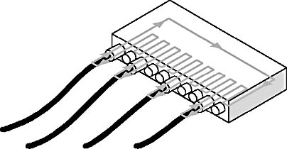
Figure 3.26 Hub showing the internal ring and clockwise token path
Hub Capacity
An IBM MSAU has 10 connection ports. It can connect up to eight computers. However, a Token Ring network is not limited to one ring (hub). Each ring can have up to 33 hubs.
Each MSAU-based network can support as many as 72 computers that use unshielded wire or up to 260 computers that use shielded wire.
Other vendors offer hubs with more capacity; the capacity depends on the vendor and the hub model.
When one Token Ring is full—that is, when every port on an MSAU has a computer connected to it—adding another ring (MSAU) can enlarge the network.
The only rule that must be followed is that each MSAU must be connected in such a way so that it becomes part of the ring. Figure 3.27 shows 1, 2, and 3 MSAU connected and maintaining a logical ring. An MSAU's ring-in and ring-out connection points make use of patch cables to connect many MSAUs on top of each other while still forming a continuous ring inside the MSAUs.
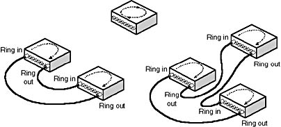
Figure 3.27 Adding hubs while maintaining the logical ring
Built-in Fault Tolerance
In a pure token-passing network, a computer that fails stops the token from continuing. This in turn brings down the network. MSAUs were designed to detect when a NIC fails, and to disconnect from it. This procedure bypasses the failed computer so that the token can continue on.
In IBM's MSAUs, bad MSAU connections or computers are automatically by-passed and disconnected from the ring. Therefore, a faulty computer or connection will not affect the rest of the Token Ring network.
Cabling
The STP or UTP cable to a hub connects computers on a Token Ring network. Figure 3.28 shows cable length limits for three types of cabling. Token Rings use IBM Type 1, 2, and 3 cabling. Most networks use IBM Cabling System Type 3 UTP cabling.
Each computer can be no more than 101 meters (330 feet) from an MSAU when connected with Type 1 cable. Each computer can be up to 100 meters (about 328 feet) from the MSAU when STP cabling is used, or 45 meters (about 148 feet) when UTP cabling is used. The minimum length for shielded or unshielded cable is 2.5 meters (about 8 feet).
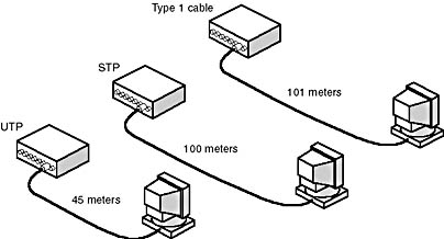
Figure 3.28 Maximum hub to computer distances on Type 1, STP, and UTP cables
According to IBM, the maximum cabling distance from an MSAU to a computer or a file server is 46 meters (150 feet) when Type 3 cabling is used. Some vendors, however, claim that data transmission can be reliable for up to 152 meters (500 feet) between an MSAU and a computer.
The maximum distance from one MSAU to another is limited to 152 meters (500 feet). Each single Token Ring can accommodate only 260 computers with STP cable and 72 computers with UTP cable.
Patch Cables
Patch cables extend the connection between a computer and an MSAU. They can also join two MSAUs together. In the IBM cabling system, these are Type 6 cables and can be any length up to 46 meters (150 feet). Patch cable will allow only 46 meters between a computer and an MSAU.
The IBM cabling system also specifies a Type 6 patch cable for:
- Increasing the length of Type 3 cables.
- Connecting computers to MSAUs directly.
Connectors
Token Ring networks usually join cables to components with the following types of connectors:
- Media interface connectors (MICs) for connecting Types 1 and 2 cable. These are IBM Type A connectors, known elsewhere as universal data connectors. They are neither male nor female; you can connect one to another by flipping either one over.
- RJ-45 telephone connectors (8-pin) for Type 3 cable.
- RJ-11 telephone connectors (4-pin) for Type 3 cable.
- Media filters to make the connection between the Token Ring NIC and a standard RJ-11/RJ-45 telephone jack (outlet).
Media Filters
Media filters are required in computers that use Type 3 telephone twisted-pair cabling, because they convert cable connectors and reduce line noise.
Patch Panels
A patch panel is used to organize cable that runs between a MSAU and a telephone punchdown block. (Patch panels are discussed further later in this chapter. A punchdown block is a kind of hardware that provides terminal connections for bare network cable ends.)
Repeaters
Using repeaters can increase all Token Ring cable distances. A repeater actively regenerates and retimes the Token Ring signal to extend distances between MSAUs on the network. Using one pair of repeaters, MSAUs can be located up to 365 meters (1200 feet) apart using Type 3 cable, or 730 meters (2400 feet) apart using Type 1 or 2 cable.
Network Interface Cards
Token Ring NICs are available in both 4-Mbps and 16-Mbps models. The 16-Mbps cards accommodate an increased frame length that requires fewer transmissions for the same amount of data.
Implementing Token Ring cards requires caution because a Token Ring network will run at only one of two possible speeds: 4 Mbps or 16 Mbps. If the network is a 4-Mbps network, the 16-Mbps cards can be used because they will revert back to 4-Mbps mode. A 16-Mbps network, however, will not accept the slower 4-Mbps cards because they cannot increase speed.
Although several manufacturers make Token Ring NICs and other Token Ring components, IBM currently sells the majority of them.
Fiber-Optic Cable
Because of the mix of data streaming (streaming is an undifferentiated, byte-by-byte flow of data), high speeds, and data traveling in one direction only, Token Ring networks are well suited to fiber-optic cable. Though more expensive, fiber-optic cable can greatly increase the range of a Token Ring network—up to 10 times what copper cabling allows.
The Future of Token Ring Networks
At the beginning of this lesson it was mentioned that Token Ring was losing market share to Ethernet. Even though Ethernet is more popular, token-ring technology is still active and growing. Many large companies are selecting TokenRing to support mission-critical applications. These networks are bridged networks (that is, connected by means of bridges) that carry protocols (see Chapter 6, "Defining Network Protocols," for more information) such as Systems Network Architecture (SNA), NetBIOS, Transmission Control Protocol/Internet Protocol (TCP/IP); and IPX. LAN-based applications such as electronic mail, software distribution, and imaging are driving the growth. Meeting the expansion needs of the large company is accomplished by adding new rings using bridges. Typically, each ring accommodates from 50 to 80 users. Token Ring users today face the following challenges:
- Complexities, manageability, cost, and space requirements for many two-port bridges
- Bridge congestion
- Segment congestion
- Upgrading to high-speed technologies
A recent and relatively new concept for Token Ring networks is the use of switches to provide high-performance, low-cost alternatives to using bridges and routers. The idea of switching is to move a device from one Token Ring to another electronically. These switches operate like an electronic patch panel. Hub vendors offer a variety of these new Token Ring switchers.
Lesson Summary
Table 3.10 summarizes the specifications for Token Ring architecture presented in this lesson. It outlines the minimum set of standards required to conform to IEEE specifications. A particular implementation of the network architecture might differ from the information in this table.
Table 3.10 Token Ring Specifications
| IEEE specification | Token Ring |
|---|---|
| Topology | Star ring |
| Cable type | Shielded or unshielded twisted-pair cable |
| Terminator resistance, Ω (ohms) | Not applicable |
| Impedance, Ω | 100_120 UTP, 150 STP |
| Maximum cable segment length | From 45 to 200 meters (about 148 to 656 feet), depends on cable type |
| Minimum length between computers | 2.5 meters (about 8 feet) |
| Maximum connected segments | 33 multistation access units (MSAUs) |
| Maximum computers per segment | Unshielded: 72 computers per hub; Shielded: 260 computers per hub |
EAN: 2147483647
Pages: 106