Placement of Integrity Control Systems
The same approaches to positioning host-level intrusion detection systems are applicable to integrity control systems.
Placing Deception Systems
As we saw earlier, the deception system can be implemented using one of two methods. The first approach is based on the emulation of specific services or vulnerabilities located only on the computer where the deception system is running (for example, RealSecure Server Sensor or DTK use this approach). The second method implies emulating other hosts or even network segments containing virtual hosts (systems like CyberCop Sting or ManTrap are based on this method). In the first case, when the deception system is placed on the protected host, selecting its location does not present any problems, while systems of the second type may not be as straightforward.
Recourse Technologies (http://www.recourse.com), recently purchased by Symantec, has come up with quite an interesting solution. Its original deception system, known as ManTrap, is located in a separate segment of the corporate network. The traffic that passes via the firewall is split into two directions. Normal queries (for example, SMTP or HTTP) are transmitted as usual - into the demilitarized zone. All other queries, which should not reach the production servers (Telnet, for example), are directed to the deception system, which serves as a signal of unauthorized activity (Fig. 10.23). To implement this redirection, one can use the built-in router mechanisms (for example, the built-in mechanisms of the Cisco IOS 12.x operating system).
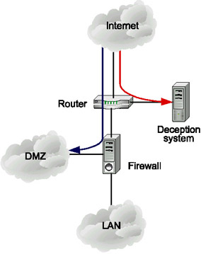
Fig. 10.23. The first approach to deception system placement
However, this configuration does not replace the classical model of intrusion detection systems in any way, since attacks against existing applications or services will not be redirected to the deception system.
Another way to place the deception system is to position it in a controlled network segment (Fig. 10.24). The host with the deception system is connected to the same switch or hub as the production hosts, and has a slightly different address from those of the production hosts. For example, the IP address of the database server, file server, and domain controller are 192.168.0.100, 192.168.0.254, and 192.168.0.1, respectively, while the address of the deception system is 192.168.0.200. When the intruder falls into a trap while determining an attack target by means of network mapping, this serves as a signal to the security administrator. Besides an IP address very similar to those used in the production environment, the deception system might have a DNS name that is phonetically similar. Several different names or IP addresses can map to the same system using aliases.
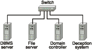
Fig. 10.24. The second approach to positioning the deception system
EAN: 2147483647
Pages: 152