7.1 Systems coding outline
7.1 Systems coding outline
The MPEG-1 standard gives the syntax description of how audio, video and data are combined into a single data stream. This sequence is formally termed the ISO 11172 stream [3]. The structure of this ISO 11172 stream is illustrated in Figure 7.1. It consists of a compression layer and a systems layer. In this book we study only the video part of the compression layer, but the systems layer is important for the proper delivery of the coded bit stream to the video decoder, and hence we briefly describe it.
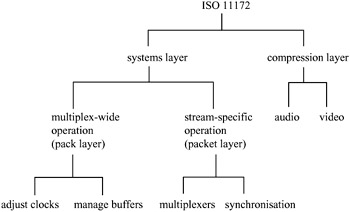
Figure 7.1: Structure of an ISO 11172 stream
The MPEG-1 systems standard defines a packet structure for multiplexing coded audio and video into one stream and keeping it synchronised. The systems layer is organised into two sublayers known as the pack and packet layers. A pack consists of a pack header that gives the systems clock reference (SCR) and the bit rate of the multiplexed stream followed by one or more packets. Each packet has its own header that conveys essential information about the elementary data that it carries. The aim of the systems layer is to support the combination of video and audio elementary streams. The basic functions are as follows:
-
synchronised presentation of decoded streams
-
construction of the multiplexed stream
-
initialisation of buffering for playback start-up
-
continuous buffer management
-
time identification.
In the systems layer, elements of direct interest to the video encoding and decoding processes are mainly those of the stream-specific operations, namely multiplexing and synchronisation.
7.1.1 Multiplexing elementary streams
The multiplexing of elementary audio, video and data is performed at the packet level. Each packet thus contains only one elementary data type. The systems layer syntax allows up to 32 audio, 16 video and two data streams to be multiplexed together. If more than two data streams are needed, substreams may be defined.
7.1.2 Synchronisation
Multiple elementary streams are synchronised by means of presentation time stamps (PTS) in the ISO 11172 bit stream. End-to-end synchronisation is achieved when the encoders record time stamps during capture of raw data. The receivers will then make use of these PTS in each associated decoded stream to schedule their presentations. Playback synchronisation is pegged onto a master time base, which may be extracted from one of the elementary streams, the digital storage media (DSM), channel or some external source. This prototypical synchronisation arrangement is illustrated in Figure 7.2. The occurrences of PTS and other information such as the systems clock reference (SCR) and systems headers will also be essential for facilitating random access of the MPEG-1 bit stream. This set of access codes should therefore be located near to the part of the elementary stream where decoding can begin. In the case of video, this site will be near the head of an intraframe.
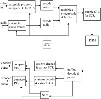
Figure 7.2: MPEG-1's prototypical encoder and decoder illustrating end-to-end synchronisation (STC— systems time clock; SCR— systems clock reference; PTS— presentation time stamp; DSM— digital storage media)
To ensure guaranteed decoder buffer behaviour, the MPEG-1 systems layer employs a systems target decoder (STD) and decoding time stamp (DTS). The DTS differs from PTS only in the case of video pictures that require additional reordering delay during the decoding process.
EAN: 2147483647
Pages: 148