The source material for video coding may exist in a variety of forms such as computer files or live video in CCIR-601 format [4]. If CCIR-601 is the source, since MPEG-1 is for coding of video at VCR
Because of the conflicting requirements of random access and highly efficient coding, the MPEG suggested that not all pictures of a video sequence should be coded in the same way. They identified four types of picture in a video sequence. The first type is called I-pictures, which are coded without reference to the previous picture. They provide access points to the coded sequence for decoding. These pictures are intraframe coded as for JPEG, with a moderate compression. The second type is the P-pictures, which are predictively coded with reference to the previous I or P-coded pictures. They
If B-pictures are not used for predictions of future
In applications such as transmission of video over packet networks, B-pictures may be discarded (e.g. due to buffer overflow) without
Figure 7.3 illustrates the relationship between these three types of picture. Since B-pictures use I and P-pictures as predictions, they have to be coded later. This requires reordering the incoming picture order, which is carried out at the preprocessor.
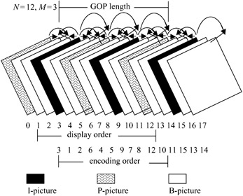
Figure 7.3:
An example of MPEG-1 GOP
The fourth picture type is the D-pictures. These are intraframe coded, where only the DC coefficients are retained. Hence the picture quality is poor and normally used for applications like fast forward. D-pictures are not part of the GOP, hence they are not present in a sequence containing any other picture type.
Since in the H.261 standard successive
The GOP length is normally defined as the distance between I-pictures, which is represented by parameter N in the standard codecs. The distance between the anchor I/P to P-pictures is represented by M. In the above Figure N = 12 and M = 3. The group of pictures may be of any length, but there should be at least one I-picture in each GOP. Applications requiring random access, fast forward play or fast and normal reverse play may use short GOPs. GOP may also start at scene cuts or other cases where motion compensation is not effective. The number of consecutive B-pictures is variable. Neither a P nor a B-picture needs to be present. For most applications, GOP in the SIF-625/50 format has N = 12 and M = 3. In SIF-525/60, the values are 15 and 3, respectively.
The encoding or transmission order of pictures
All the three main picture types, I, P and B, have the same SIF
Each picture is divided into a group of macroblocks, called slices. In H.261 such a group was called GOB. The reason for defining a slice is the same as that for defining a GOB, namely resetting the variable length code to prevent channel error propagation into the picture. Slices can have different sizes within a picture, and the division in one picture need not be the same as the division in any other picture.
The slices can begin and end at any macroblock in a picture, but with some constraints. The first slice must begin at the top left of the picture (the first macroblock) and the end of the last slice must be the bottom right macroblock (the last
|
1 begin |
end 1 |
|
2 begin |
end 2 |
|
3 begin |
end 3 |
|
4 begin |
end 4 |
|
5 begin |
end 5 |
|
6 begin |
end 6 |
|
7 be in |
end 7 |
|
8 begin |
end 8 |
|
9 begin |
end 9 |
|
10 be in |
end 10 |
|
11 be in |
end 11 |
|
12 begin |
end 12 |
|
13 begin |
end 13 |
|
14 egin |
end 14 |
|
1 egin |
end 15 |
|
11 legin |
end 16 |
|
17 begin |
end 17 |
|
18 begin |
end 18 |
Each slice starts with a slice start code, and is followed by a code that defines its position and a code that sets the quantisation step size. Note that in H.261 the quantisation step sizes were set at each GOB or row of GOBs, but in MPEG-1 they can be set at any macroblock (see below). Therefore, in MPEG-1 the main reason for defining slices is not to reset a new quantiser, but to prevent the effects of channel error propagation. If the coded data is corrupted, and the decoder detects it, then it can search for the new slice, and the decoding starts from that point. Part of the picture slice from the start of the error to the next slice can then be degraded. Therefore in a
To optimise the slice structure, that is, to give a good immunity from channel errors and at the same time to minimise the slice overhead, one might use short slices for macroblocks with significant energy (such as intra-MB), and long slices for less significant ones (e.g. macroblocks in B-pictures). Figure 7.5 shows a slice structure where in some
Figure 7.5:
Possible arrangement of slices in SIF-625
Slices are divided into macroblocks of 16 × 16 pixels, similar to the division of GOB into macroblocks in H.261. Macroblocks in
The first difference is that since a slice has a raster scan structure, macroblocks are addressed in a raster scan order. The top left macroblock in a picture has address 0, the next one on the right has address 1 and so on. If there are
M
macroblocks in a picture (e.g.
M =
396), then the bottom right macroblock has address
M -
1. To reduce the address overhead, macroblocks are relatively addressed by transmitting the difference between the current macroblock and the previously coded macroblock. This difference is called the macroblock address increment. In I-pictures, since all the macroblocks are coded, the macroblock address increment is always 1. The exception is that, for the first coded macroblock at the beginning of each slice, the macroblock address is set to that of the right-hand macroblock of the previous row. This address at the beginning of each picture is set to -1. If a slice does not start at the left edge of the picture (see the slice structure of Figure 7.5), then the macroblock address increment for the first macroblock in the slice will be larger than one. For example, in the slice structure of Figures 7.4 and 7.5 there are 22 macroblocks per row. For Figure 7.4, at the start of slice two, the macroblock address is set to 21, which is the address of the macroblock at the right-hand edge of the top row of macroblocks. In Figure 7.5, if the first slice contains 30 macroblocks, eight of them would be in the second row, so the address of the first macroblock in the second slice would be 30 and the macroblock increment would be nine. For further reduction of address overhead, macroblock address
There is no code to
Finally, the smallest part of the picture structure is the block of 8 × 8 pixels, for both luminance and chrominance
Figure 7.6:
MPEG-1 coded video structure