7.3 Video structure
7.3 Video structure
7.3.1 Group of pictures (GOP)
Since in the H.261 standard successive frames are similarly coded, a picture is the top level of the coding hierarchy. In MPEG-1 due to the existence of several picture types, a group of pictures, called GOP, is the highest level of the hierarchy. A GOP is a series of one or more pictures to assist random access into the picture sequence. The first coded picture in the group is an I-picture. It is followed by an arrangement for P and B-pictures, as shown in Figure 7.3.
The GOP length is normally defined as the distance between I-pictures, which is represented by parameter N in the standard codecs. The distance between the anchor I/P to P-pictures is represented by M. In the above Figure N = 12 and M = 3. The group of pictures may be of any length, but there should be at least one I-picture in each GOP. Applications requiring random access, fast forward play or fast and normal reverse play may use short GOPs. GOP may also start at scene cuts or other cases where motion compensation is not effective. The number of consecutive B-pictures is variable. Neither a P nor a B-picture needs to be present. For most applications, GOP in the SIF-625/50 format has N = 12 and M = 3. In SIF-525/60, the values are 15 and 3, respectively.
The encoding or transmission order of pictures differs from the display or incoming picture order. In the Figure B-pictures 1 and 2 are encoded after P-picture 0 and I-picture 3 are encoded. Also in this Figure B-pictures 13 and 14 are a part of the next GOP. Although their display order is 0,1,2,...,11, their encoding order is 3,1,2,6,4,5.. .. This reordering introduces delays amounting to several frames at the encoder (equal to the number of B-pictures between the anchor I and P-pictures). The same amount of delay is introduced at the decoder, in putting the transmission/decoding sequence back to its original. This format inevitably limits the application of MPEG-1 for telecommunications.
7.3.2 Picture
All the three main picture types, I, P and B, have the same SIF size with 4:2:0 format. In SIF-625 the luminance part of each picture has 360 pixels, 288 lines and 25 Hz, and those of each chrominance are 180 pixels, 144 lines and 25 Hz. In SIF-525, these values for luminance are 360 pixels, 240 lines and 30 Hz, and for the chrominance are 180, 120 and 30, respectively. For 4:2:0 format images, the luminance and chrominance samples are positioned as shown in Figure 2.3.
7.3.3 Slice
Each picture is divided into a group of macroblocks, called slices. In H.261 such a group was called GOB. The reason for defining a slice is the same as that for defining a GOB, namely resetting the variable length code to prevent channel error propagation into the picture. Slices can have different sizes within a picture, and the division in one picture need not be the same as the division in any other picture.
The slices can begin and end at any macroblock in a picture, but with some constraints. The first slice must begin at the top left of the picture (the first macroblock) and the end of the last slice must be the bottom right macroblock (the last macroblock) of the picture, as shown in Figure 7.4. Therefore the minimum number of slices per picture is one, and the maximum number is equal to the number of macroblocks (e.g. 396 in SIF-625).
| 1 begin | end 1 |
| 2 begin | end 2 |
| 3 begin | end 3 |
| 4 begin | end 4 |
| 5 begin | end 5 |
| 6 begin | end 6 |
| 7 be in | end 7 |
| 8 begin | end 8 |
| 9 begin | end 9 |
| 10 be in | end 10 |
| 11 be in | end 11 |
| 12 begin | end 12 |
| 13 begin | end 13 |
| 14 egin | end 14 |
| 1 egin | end 15 |
| 11 legin | end 16 |
| 17 begin | end 17 |
| 18 begin | end 18 |
Figure 7.4: An example of slice structure for SIF-625 pictures
Each slice starts with a slice start code, and is followed by a code that defines its position and a code that sets the quantisation step size. Note that in H.261 the quantisation step sizes were set at each GOB or row of GOBs, but in MPEG-1 they can be set at any macroblock (see below). Therefore, in MPEG-1 the main reason for defining slices is not to reset a new quantiser, but to prevent the effects of channel error propagation. If the coded data is corrupted, and the decoder detects it, then it can search for the new slice, and the decoding starts from that point. Part of the picture slice from the start of the error to the next slice can then be degraded. Therefore in a noisy environment it is desirable to have as many slices as possible. On the other hand each slice has a large overhead, called slice start code (minimum of 32 bits). This creates a large overhead in the total bit rate. For example, if we use the slice structure of Figure 7.4, where there is one slice for each row of MBs, then for SIF-625 video there are 18 slices per picture, and with 25 Hz video, the slice overhead can be 32 × 18 × 25 = 14 400 bit/s.
To optimise the slice structure, that is, to give a good immunity from channel errors and at the same time to minimise the slice overhead, one might use short slices for macroblocks with significant energy (such as intra-MB), and long slices for less significant ones (e.g. macroblocks in B-pictures). Figure 7.5 shows a slice structure where in some parts the slice length extends beyond several rows of macroblocks, and in some cases is less than one row.
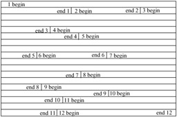
Figure 7.5: Possible arrangement of slices in SIF-625
7.3.4 Macroblock
Slices are divided into macroblocks of 16 × 16 pixels, similar to the division of GOB into macroblocks in H.261. Macroblocks in turn are divided into blocks, for coding. In Chapter 6, we gave a detailed description of how a macroblock was coded, starting from its type, mode of selection, blocks within the MB, their positional addresses and finally the block pattern. Since MPEG-1 is also a macroblock-based codec, most of these rules are used in MPEG-1. However, due to differences of slice versus GOB, picture type versus a single picture format in H.261, there are bound to be variations in the coding. We first give a general account of these differences then, in the following section, more details about the macroblocks in the various picture types.
The first difference is that since a slice has a raster scan structure, macroblocks are addressed in a raster scan order. The top left macroblock in a picture has address 0, the next one on the right has address 1 and so on. If there are M macroblocks in a picture (e.g. M = 396), then the bottom right macroblock has address M - 1. To reduce the address overhead, macroblocks are relatively addressed by transmitting the difference between the current macroblock and the previously coded macroblock. This difference is called the macroblock address increment. In I-pictures, since all the macroblocks are coded, the macroblock address increment is always 1. The exception is that, for the first coded macroblock at the beginning of each slice, the macroblock address is set to that of the right-hand macroblock of the previous row. This address at the beginning of each picture is set to -1. If a slice does not start at the left edge of the picture (see the slice structure of Figure 7.5), then the macroblock address increment for the first macroblock in the slice will be larger than one. For example, in the slice structure of Figures 7.4 and 7.5 there are 22 macroblocks per row. For Figure 7.4, at the start of slice two, the macroblock address is set to 21, which is the address of the macroblock at the right-hand edge of the top row of macroblocks. In Figure 7.5, if the first slice contains 30 macroblocks, eight of them would be in the second row, so the address of the first macroblock in the second slice would be 30 and the macroblock increment would be nine. For further reduction of address overhead, macroblock address increments are VLC coded.
There is no code to indicate a macroblock address increment of zero. This is why the macroblock address is set to -1 rather than zero at the top of the picture. The first macroblock will have an increment of one, making its address equal to zero.
7.3.5 Block
Finally, the smallest part of the picture structure is the block of 8 × 8 pixels, for both luminance and chrominance components. DCT coding is applied at this block level. Figure 7.6 illustrates the whole structure of partitioning a video sequence, from its GOP level at the top to the smallest unit of block at the bottom.
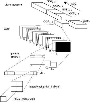
Figure 7.6: MPEG-1 coded video structure
EAN: 2147483647
Pages: 148