BGP Configurations
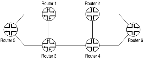
| The examples in this section use the topology shown in Figure 14.1. Figure 14.1. BGP Configuration Topology Table 14.1 lists the router loopback addresses. Table 14.2 lists the router interface addresses. Table 14.1. BGP Configuration: Router Loopback Addresses
Table 14.2. BGP Configuration: Router Interface Addresses
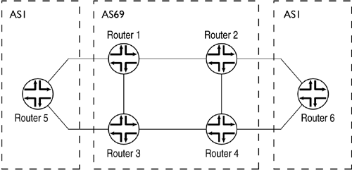
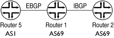
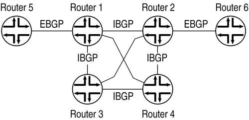
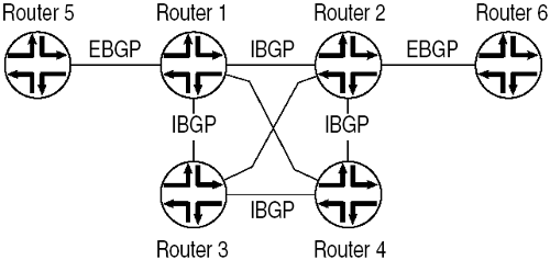
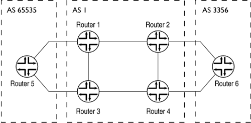
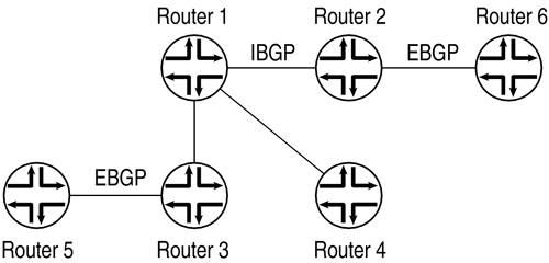
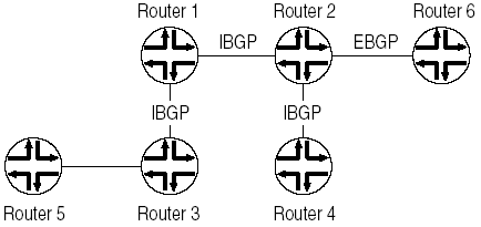
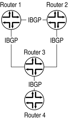
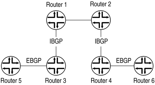
Basic BGP ConfigurationThe basic BGP configuration for the six routers in the sample topology is similar. The following sample, for Router 1, shows the snippets of the configuration related to the basic BGP configuration: routing-options { router-id 10.1.71.80; autonomous-system 69; } protocols { bgp { nlri any; group toR2 { type internal; local-address 10.1.71.80; peer-as 69; neighbor 10.1.71.83; } group toR5 { type external; peer-as 1; neighbor 192.168.100.62; } } isis { interface all { level 1 disable; level 2 metric 10; } } ospf { area 0.0.0.0 { interface all { metric 10; } interface fxp0.0 { disable; } } } } BGP Routing PolicyThe examples in this section use the ASs shown in Figure 14.2. AS 69 uses IS-IS as its IGP. EBGP peering is being configured between Router 5 and Router 1, and IBGP peering between Router 1 and Router 2. Figure 14.2. BGP Routing Policy Configuration Router 5 Configuration routing-options { router-id 10.1.71.81; autonomous-system 1; } protocols { bgp { nlri any; group toR1 { type external; export nts; peer-as 69; neighbor 192.168.100.61; } } } policy-options { policy-statement nts { from protocol static; then { metric 50; community add ntsR5; accept; } } community ntsR5 members 69:1000; } Router 1 Configuration routing-options { router-id 10.1.71.80; autonomous-system 69; } protocols { bgp { nlri any; group toR2 { type internal; local-address 10.1.71.80; peer-as 69; neighbor 10.1.71.83; } group toR5 { type external; peer-as 1; neighbor 192.168.100.62; } } isis { interface all { level 1 disable; level 2 metric 10; } } } Router 2 Configuration routing-options { router-id 10.1.71.83; autonomous-system 69; } protocols { bgp { nlri any; group toR1 { type internal; local-address 10.1.71.83; peer-as 69; neighbor 10.1.71.80; } } isis { interface all { level 1 disable; level 2 metric 10; } } } Route AggregationRoute aggregation allows routes to be grouped together and an-nounced as a single route to other BGP speakers . Aggregate routes can be used to perform aggregation as well as to modify aggregation related path attributes, such as AGGREGATOR and ATOMIC_AGGREGATE. The example in this section assumes the topology shown in Figure 14.3. Figure 14.3. BGP Route Aggregation Topology To enable route aggregation, specify the routes to aggregate with the aggregate statement and configure a BGP export policy to distribute the aggregate routes: routing-options { aggregate { route 199.1.0.0/16; } router-id 10.1.71.80; autonomous-system 69; } protocols { bgp { nlri any; export redistribute-aggregate; group toR2 { type internal; local-address 10.1.71.80; peer-as 69; neighbor 10.1.71.83; } group toR5 { type external; peer-as 1; neighbor 192.168.100.62; } } } policy-options { policy-statement redistribute-aggregate { from protocol aggregate; then accept; } } Controlling PeeringThe example in this section assumes the topology shown in Figure 14.4. The routers within AS 69 ”Router 1, Router 2, Router 3, and Router 4 ”are fully meshed. The interfaces on all these routers are configured with the same IGP metric. Figure 14.4. BGP Peering Topology Router 1 Configuration routing-options { router-id 10.1.71.80; autonomous-system 69; } protocols { bgp { keep all; nlri any; group int { type internal; local-address 10.1.71.80; peer-as 69; neighbor 10.1.71.77; neighbor 10.1.71.81; neighbor 10.1.71.78; } group extR5 { type external; peer-as 1; neighbor 192.168.100.66; } } isis { export redist-direct; interface all { level 1 disable; level 2 metric 10; } interface fxp0.0 { disable; } } } policy-options { policy-statement redist-direct { from protocol direct; then accept; } } Router 2 Configuration routing-options { router-id 10.1.71.83; autonomous-system 1; } protocols { bgp { nlri any; group internal { type internal; local-address 10.1.71.83; peer-as 1; neighbor 10.1.71.80; neighbor 10.1.71.82; neighbor 10.1.71.85; } group toR6 { type external; peer-as 3356; neighbor 192.168.100.109; } } isis { interface all { level 1 disable; level 2 metric 10; } } } Router 3 Configuration routing-options { router-id 10.1.71.82; autonomous-system 69; } protocols { bgp { group extR1 { type external; export redist-static; peer-as 69; neighbor 192.168.100.65; } } isis { interface all { level 1 disable; level 2 metric 10; } } } Router 4 Configuration routing-options { router-id 10.1.71.85; autonomous-system 69; } protocols { bgp { nlri any; group internal { type internal; local-address 10.1.71.85; peer-as 1; neighbor 10.1.71.80; neighbor 10.1.71.83; neighbor 10.1.71.82; } } isis { interface all { level 1 disable; level 2 metric 10; } } } Router 5 Configuration routing-options { router-id 10.1.71.81; autonomous-system 1; } protocols { bgp { keep all; nlri any; group int { type internal; local-address 10.1.71.81; peer-as 69; neighbor 10.1.71.80; neighbor 10.1.71.77; neighbor 10.1.71.78; } } isis { export redist-direct; interface all { level 1 disable; level 2 metric 10; } interface fxp0.0 { disable; } } } policy-options { policy-statement redist-direct { from protocol direct; then accept; } } Router 6 Configuration routing-options { router-id 10.1.71.84; autonomous-system 3356; } protocols { bgp { nlri any; group toR2 { type external; export redist-static; peer-as 1; neighbor 192.168.100.110; } } } policy-options { policy-statement redist-static { from protocol static; then accept; } } Route Flap DampingThe example in this section assumes the topology shown in Figure 14.5. The routers within AS 69 ”Router 1, Router 2, Router 3, and Router 4 ”are fully meshed. The interfaces on all these routers are configured with the same IGP metric. Figure 14.5. BGP Route Flap Damping Topology To configure route-flap damping on R1, include the damping statement when configuring BGP: protocols { bgp { damping; nlri any; group internal { type internal; local-address 10.1.71.80; peer-as 1; neighbor 10.1.71.83; neighbor 10.1.71.82; neighbor 10.1.71.85; } } } Route ReflectorsThe example in this section assumes the topology shown in Figure 14.6. Figure 14.6. BGP Route Reflector Topology Single Route ReflectorIn this example, Router 1 is the route reflector, and Router 3 and Router 4 are clients of Router 1, as shown in Figure 14.7. Figure 14.7. BGP Single Route Reflector Topology Router 1 Configuration routing-options { autonomous-system 1; } protocols { bgp { local-address 10.1.71.80; group toR3R4 { type internal; cluster 1.2.3.4; peer-as 1; neighbor 10.1.71.85; neighbor 10.1.71.82; } group toR2 { type internal; peer-as 1; neighbor 10.1.71.83; } } isis { interface all { level 1 disable; level 2 metric 10; } } } Router 3 Configuration routing-options { autonomous-system 1; } protocols { bgp { group toR1 { type internal; local-address 10.1.71.82; peer-as 1; neighbor 10.1.71.80; } group toR5 { type external; peer-as 65535; neighbor 192.168.100.129; } } isis { interface all { level 1 disable; level 2 metric 10; } } } Router 4 Configuration routing-options { autonomous-system 1; } protocols { bgp { group toR1 { type internal; local-address 10.1.71.85; peer-as 1; neighbor 10.1.71.80; } } isis { interface all { level 1 disable; level 2 metric 10; } } } Router 2 Configuration routing-options { autonomous-system 1; } protocols { bgp { group toR1 { type internal; local-address 10.1.71.83; advertise-inactive; peer-as 1; neighbor 10.1.71.80; } group toR6 { type external; peer-as 3356; neighbor 192.168.100.109; } } isis { interface all { level 1 disable; level 2 metric 10; } } } Router 5 Configuration routing-options { autonomous-system 65535; } protocols { bgp { group toR3 { type external; export redist-static; peer-as 1; neighbor 192.168.100.130; } } } policy-options { policy-statement redist-static { from protocol static; then accept; } } Router 6 Configuration routing-options { autonomous-system 3356; } protocols { bgp { export redist-static; group toR2 { type external; export redist-static; peer-as 1; neighbor 192.168.100.110; } } } Router Reflection ClusterIn this configuration, Router 1 and Router 2 are route reflectors with a cluster ID of 1.2.3.4 . Router 1 is a client of Router 1, Router 3 is a client of Router 1, and Router 4 is a regular IBGP neighbor of Router 2 (see Figure 14.8). Figure 14.8. BGP Route Reflection Cluster Topology Router 1 Configuration routing-options { autonomous-system 1; } protocols { bgp { local-address 10.1.71.80; keep all; nlri any; group toR2 { type internal; peer-as 1; neighbor 10.1.71.83; } group toR3 { type internal; cluster 1.2.3.4; peer-as 1; neighbor 10.1.71.82; } } isis { interface all { level 1 disable; level 2 metric 10; } } } Router 2 Configuration routing-options { autonomous-system 1; } protocols { bgp { nlri any; group toR6 { type external; peer-as 3356; neighbor 192.168.100.109; } group toR1 { type internal; local-address 10.1.71.83; keep all; cluster 1.2.3.4; peer-as 1; neighbor 10.1.71.80; } group toR4 { type internal; local-address 10.1.71.83; peer-as 1; neighbor 10.1.71.85; } } isis { interface all { level 1 disable; level 2 metric 10; } } } Router 3 Configuration routing-options { autonomous-system 1; } protocols { bgp { nlri any; group toR1 { type internal; local-address 10.1.71.82; peer-as 1; neighbor 10.1.71.80; } group toR5 { type external; peer-as 65535; neighbor 192.168.100.129; } } isis { interface all { level 1 disable; level 2 metric 10; } } } Router 4 Configuration routing-options { autonomous-system 1; } protocols { bgp { nlri any; export redist-static; group toR2 { type internal; local-address 10.1.71.85; peer-as 1; neighbor 10.1.71.83; } } isis { interface all { level 1 disable; level 2 metric 10; } } } policy-options { policy-statement redist-static { from protocol static; then accept; } } Router 5 Configuration routing-options { autonomous-system 65535; } protocols { bgp { nlri any; group toR3 { type external; export redist-static; peer-as 1; neighbor 192.168.100.130; } group r { peer-as 70; neighbor 192.168.5.48 { multihop; } } } isis { disable; interface all { level 1 disable; level 2 metric 10; } } } policy-options { policy-statement redist-static { from protocol static; then accept; } } Router 6 Configuration routing-options { autonomous-system 3356; } protocols { bgp { nlri any; export redist-static; group toR2 { type external; export redist-static; peer-as 1; neighbor 192.168.100.110; } group r { peer-as 10458; neighbor 208.197.169.14 { multihop; } } } } policy-options { policy-statement redist-static { from protocol static; then accept; } } Hierarchical Route ReflectionIn this configuration, Router 2 and Router 4 are the route reflectors. Router 4 in cluster 1 is a client of Router 2, and Router 3 in cluster 2 is a client of Router 4 (see Figure 14.9). Figure 14.9. BGP Hierarchical Route Reflection Topology Router 2 Configuration routing-options { autonomous-system 1; } protocols { bgp { nlri any; group toR6 { type external; peer-as 3356; neighbor 192.168.100.109; } group toR4 { type internal; local-address 10.1.71.83; cluster 1.2.3.4; peer-as 1; neighbor 10.1.71.85; } } isis { interface all { level 1 disable; level 2 metric 10; } } } Router 4 Configuration routing-options { autonomous-system 1; } protocols { bgp { local-address 10.1.71.85; nlri any; group toR3 { type internal; local-address 10.1.71.85; cluster 5.6.7.8; peer-as 1; neighbor 10.1.71.82; } group toR2 { type internal; local-address 10.1.71.85; peer-as 1; neighbor 10.1.71.83; } } isis { interface all { level 1 disable; level 2 metric 10; } } } Router 3 Configuration routing-options { autonomous-system 1; } protocols { bgp { nlri any; group toR4 { type internal; local-address 10.1.71.82; peer-as 1; neighbor 10.1.71.85; } group toR5 { type external; peer-as 65535; neighbor 192.168.100.129; } } isis { interface all { level 1 disable; level 2 metric 10; } } } Routing Loop ProtectionThis configuration uses clusters to provide protection from routing loops (see Figure 14.10). In this configuration, Router 1, Router 2, and Router 3 are the route reflectors. Router 4 is a client of Router 3 and has a cluster ID of 1.0.0.1 . Router 3 is a client of Router 1 and Router 2 and has a cluster ID of 1.0.0.2. IGP metrics are selected such that Router 2 prefers routes from Router 1 over Router 3. Figure 14.10. BGP Routing Loop Protection Topology Router 1 Configuration routing-options { autonomous-system 1; } protocols { bgp { local-address 10.1.71.80; nlri any; group toR3 { type internal; cluster 1.0.0.2; peer-as 1; neighbor 10.1.71.82; } group toR2 { type internal; peer-as 1; neighbor 10.1.71.83; } } isis { interface all { level 1 disable; level 2 metric 10; } } } Router 2 Configuration routing-options { autonomous-system 1; } protocols { bgp { keep all; nlri any; group toR3 { type internal; local-address 10.1.71.83; cluster 1.0.0.2; peer-as 1; neighbor 10.1.71.82; } group toR1 { type internal; local-address 10.1.71.83; peer-as 1; neighbor 10.1.71.80; } } isis { interface all { level 1 disable; level 2 metric 10; } } } Router 3 Configuration routing-options { autonomous-system 1; } protocols { bgp { nlri any; group toR1R2 { type internal; local-address 10.1.71.82; peer-as 1; neighbor 10.1.71.83; neighbor 10.1.71.80; } group toR4 { type internal; local-address 10.1.71.82; cluster 1.0.0.1; peer-as 1; neighbor 10.1.71.85; } } isis { interface all { level 1 disable; level 2 metric 10; } } } Router 4 Configuration routing-options { autonomous-system 1; } protocols { bgp { nlri any; export redist-static; group toR3 { type internal; local-address 10.1.71.85; peer-as 1; neighbor 10.1.71.82; } } isis { interface all { level 1 disable; level 2 metric 10; } } } ConfederationsThis example shows a router confederation between Router 1 and Router 2 (see Figure 14.11). Figure 14.11. BGP Confederation Topology Router 1 Configuration routing-options { router-id 10.1.71.80; autonomous-system 65000; confederation 32 members [ 65000 65001 ]; } protocols { bgp { multihop { ttl 6; } keep all; nlri any; group extR2 { type external; local-address 10.1.71.80; peer-as 65001; neighbor 10.1.71.83; } group int { type internal; local-address 10.1.71.80; neighbor 10.1.71.82; } } isis { export redist-direct; interface all { level 1 disable; level 2 metric 10; } interface fxp0.0 { disable; } } } policy-options { policy-statement redist-direct { from protocol direct; then accept; } } Router 2 Configuration routing-options { router-id 10.1.71.83; autonomous-system 65001; confederation 32 members [ 65000 65001 ]; } protocols { bgp { multihop { ttl 6; } keep all; nlri any; group extR1 { type external; local-address 10.1.71.83; peer-as 65000; neighbor 10.1.71.80; } group int { type internal; local-address 10.1.71.83; neighbor 10.1.71.85; } } isis { export redist-direct; interface all { level 1 disable; level 2 metric 10; } interface fxp0.0 { disable; } } } policy-options { policy-statement redist-direct { from protocol direct; then accept; } } Router 3 Configuration routing-options { router-id 10.1.71.82; autonomous-system 65000; confederation 32 members [ 65000 65001 ]; } protocols { bgp { keep all; nlri any; group extR5 { type external; local-address 192.168.100.130; peer-as 65535; neighbor 192.168.100.129; } group int { type internal; multihop { ttl 6; } local-address 10.1.71.82; neighbor 10.1.71.80; } } isis { export redist-direct; interface all { level 1 disable; level 2 metric 10; } interface fxp0.0 { disable; } } } policy-options { policy-statement redist-direct { from protocol direct; then accept; } } Router 4 Configuration routing-options { router-id 10.1.71.85; autonomous-system 65001; confederation 32 members [ 65000 65001 ]; } protocols { bgp { keep all; nlri any; group extR6 { type external; local-address 192.168.100.106; peer-as 37; neighbor 192.168.100.105; } group int { type internal; multihop { ttl 6; } local-address 10.1.71.85; neighbor 10.1.71.83; } } isis { export redist-direct; interface all { level 1 disable; level 2 metric 10; } interface fxp0.0 { disable; } } } policy-options { policy-statement redist-direct { from protocol direct; then accept; } } Router 5 Configuration routing-options { router-id 10.1.71.81; autonomous-system 65535; } protocols { bgp { group extR3 { type external; local-address 192.168.100.129; export redist-static; peer-as 32; neighbor 192.168.100.130; } } } policy-options { policy-statement redist-direct { from protocol direct; then accept; } } Router 6 Configuration routing-options { router-id 10.1.71.84; autonomous-system 37; } protocols { bgp { keep all; group extR4 { type external; local-address 192.168.100.105; export redist-static; peer-as 32; neighbor 192.168.100.106; } } } policy-options { policy-statement redist-direct { from protocol direct; then accept; } } |
EAN: 2147483647
Pages: 185
