| < Day Day Up > |
Now that you have seen how data “flows” in an MPLS network, it is time to look at some practical
The first part of these applications
Manufacturers
All manufacturers reserve labels 0–15, but they divide their labels differently. This does not affect interoperability, because labels are negotiated when an LDP is established. If a label is
With other routers (such as Cisco), you can assign a label range with a simple command figure, as shown in Figure 1.10.
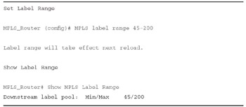
Figure 1.10:
MPLS Label Range Commands
The
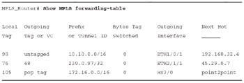
Figure 1.11:
MPLS Forwarding Table Commands
| < Day Day Up > |
| < Day Day Up > |
We find in an MPLS network that data moves from switch to switch using link-specific labels. Switches perform functions based on their switching or cross-connect tables.
These tables contain information such as port in, label in, port out, label out,
In this exercise, sample tracing of a packet through an MPLS network, five routers R1-R5 connect networks X and Z. Tables 1.4-1.8 are used to discover the LSPs. Table 1.4 is used for Router 1, Table 1.5 is used for Router 2, Table 1.6 is used for Router 3, Table 1.7 is used for Router 4, and Table 1.8 is used for Router 5. Each table is different and represents the MPLS routers internal switching table.
In Figure 1.12, we have an example of how data would move in this situation.
In Table 1.4, the packet (being HTTP port 80) enters as native IP/80 where a label (20) is
In Table 1.6, the label (20) is swapped for label 600, and the packet exits the router at port D, where it is hardwired to port B of R5.
In Table 1.8 (R5), the packet label 600 is popped to deliver a native packet to network Z.
Note that Figure 1.11 reflects the correct labels.
In this exercise, use the switching tables for Routers 1 through 5 and Figures 1.12 and 1.13 to map data flow and labeling across the network. Of course, the tables contain data that is not used for your packet, but they also contain switching data needed for other packets. Use only the data that you need to move your packets. Follow these instructions:
Always start with Table 1.4 and follow applications that enter through Interface A.
|
P_In |
Label In |
Label Out |
Port Out |
Instruction |
Next Router |
|---|---|---|---|---|---|
|
IP/80 |
None |
20 |
D |
Push |
R3 |
|
IP/25 |
None |
95 |
B |
Push |
R4 |
|
IP/20 |
None |
500 |
C |
Push |
R2 |
The decision made by Table 1.4 will lead you to another switching table, depending on the application, port out, and the router out.
In Figure 1.12, note that the packet label
Figure 1.12:
Network Trace for HTTP Port Number 80
Use Figure 1.13 and Tables 1.4-1.8 to trace e-mail (port 25) through the network, and note the trace on the drawing.
Figure 1.13:
Network Trace for Port 25 E-Mail
|
P_In |
Label In |
Label Out |
Port Out |
Instruction |
Next Router |
|---|---|---|---|---|---|
|
B |
499 |
700 |
D |
Swap |
R5 |
|
B |
500 |
65 |
C |
Swap |
R3 |
|
B |
501 |
700 |
A |
Swap |
R9 |
|
P_In |
Label In |
Label Out |
Port Out |
Instruction |
Next Router |
|---|---|---|---|---|---|
|
B |
20 |
600 |
D |
Swap |
R5 |
|
A |
65 |
650 |
D |
Swap |
R5 |
|
B |
501 |
700 |
A |
Swap |
R9 |
Using Figure 1.14 and Tables 1.4-1.8 to trace FTP (port 20) through the network, and note the trace on the drawing.
Figure 1.14:
Network Trace for Port 20 FTP
|
P_In |
Label In |
Label Out |
Port Out |
Instruction |
Next Router |
|---|---|---|---|---|---|
|
B |
95 |
710 |
D |
Push |
R5 |
|
A |
500 |
650 |
D |
Push |
R5 |
|
B |
515 |
700 |
D |
Push |
R5 |
|
P_In |
Label In |
Label Out |
Port Out |
Instruction |
Next Router |
|---|---|---|---|---|---|
|
A |
500 |
None |
D |
Pop |
CR |
|
B |
600 |
None |
D |
Pop |
CR |
|
B |
650 |
None |
D |
Pop |
CR |
|
C |
710 |
None |
D |
Pop |
CR |
| < Day Day Up > |