Exercise 1.2: MPLS Data Flow
|
| < Day Day Up > |
|
We find in an MPLS network that data moves from switch to switch using link-specific labels. Switches perform functions based on their switching or cross-connect tables.
These tables contain information such as port in, label in, port out, label out, next router, and instructions. The instructions are simple: 'push' (insert a label), 'swap' (change labels), and 'pop' (remove label).
In this exercise, sample tracing of a packet through an MPLS network, five routers R1-R5 connect networks X and Z. Tables 1.4-1.8 are used to discover the LSPs. Table 1.4 is used for Router 1, Table 1.5 is used for Router 2, Table 1.6 is used for Router 3, Table 1.7 is used for Router 4, and Table 1.8 is used for Router 5. Each table is different and represents the MPLS routers internal switching table.
In Figure 1.12, we have an example of how data would move in this situation.
In Table 1.4, the packet (being HTTP port 80) enters as native IP/80 where a label (20) is pushed and the packet is sent out of port D. Notice that as the packet traverses the network, it exits Router 1 at port D and enters Router 3 at port B.
In Table 1.6, the label (20) is swapped for label 600, and the packet exits the router at port D, where it is hardwired to port B of R5.
In Table 1.8 (R5), the packet label 600 is popped to deliver a native packet to network Z.
Note that Figure 1.11 reflects the correct labels.
In this exercise, use the switching tables for Routers 1 through 5 and Figures 1.12 and 1.13 to map data flow and labeling across the network. Of course, the tables contain data that is not used for your packet, but they also contain switching data needed for other packets. Use only the data that you need to move your packets. Follow these instructions:
-
Always start with Table 1.4 and follow applications that enter through Interface A.
Table 1.4: Switching Table for Router 1 P_In
Label In
Label Out
Port Out
Instruction
Next Router
IP/80
None
20
D
Push
R3
IP/25
None
95
B
Push
R4
IP/20
None
500
C
Push
R2
-
The decision made by Table 1.4 will lead you to another switching table, depending on the application, port out, and the router out.
-
In Figure 1.12, note that the packet label numbers appear on the drawings. Use Figures 1.13 and 1.14 to indicate the correct label number.
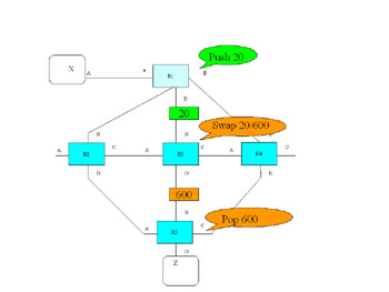
Figure 1.12: Network Trace for HTTP Port Number 80 -
Use Figure 1.13 and Tables 1.4-1.8 to trace e-mail (port 25) through the network, and note the trace on the drawing.
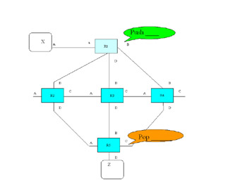
Figure 1.13: Network Trace for Port 25 E-MailTable 1.5: Switching Table for Router 2 P_In
Label In
Label Out
Port Out
Instruction
Next Router
B
499
700
D
Swap
R5
B
500
65
C
Swap
R3
B
501
700
A
Swap
R9
Table 1.6: Switching Table for Router 3 P_In
Label In
Label Out
Port Out
Instruction
Next Router
B
20
600
D
Swap
R5
A
65
650
D
Swap
R5
B
501
700
A
Swap
R9
-
Using Figure 1.14 and Tables 1.4-1.8 to trace FTP (port 20) through the network, and note the trace on the drawing.
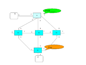
Figure 1.14: Network Trace for Port 20 FTPTable 1.7: Switching Table for Router 4 P_In
Label In
Label Out
Port Out
Instruction
Next Router
B
95
710
D
Push
R5
A
500
650
D
Push
R5
B
515
700
D
Push
R5
Table 1.8: Switching Table for Router 5 P_In
Label In
Label Out
Port Out
Instruction
Next Router
A
500
None
D
Pop
CR
B
600
None
D
Pop
CR
B
650
None
D
Pop
CR
C
710
None
D
Pop
CR
|
| < Day Day Up > |
|
EAN: 2147483647
Pages: 138