Case Studies and Sample Configurations
| The following case studies represent a scaled-down version of an enterprise network. In real topologies, much more redundancy would be built into the network topology. However, for clarity and conciseness, the topology has been reduced to the critical network elements themselves. The network core consists of Catalyst 6500s, which branch off distribution switches at the company's east and west campuses. The distribution layer switches in this case are represented by the Catalyst 4507Rs at each campus. A 7200VXR router serves as the headend for the company's branch locations. Frame relay circuits extend the network to each branch, represented with a 3745 router. The topology described above is illustrated in Figure 11-6. Figure 11-6. Case Study PKI Topology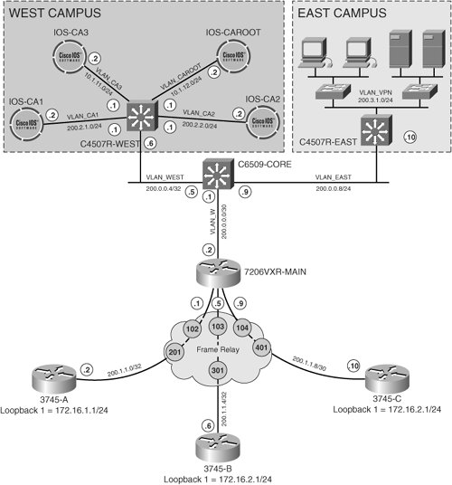 Critical resources are located at the company's east campus. Transmissions from these resources across the WAN to the branch offices must be kept confidential. Security administrators have selected asymmetric encryption as the method used to authenticate the IKE channels. As such, a PKI-based implementation has been chosen to encrypt data from the company's east campus to resources at the branch locations. This series of case studies will demonstrate various PKI deployments in the company's west campus that are used to deliver these services. Case Study 1: PKI Integration of Cryptographic EndpointsIn the first case study, we will illustrate the basic enrollment and authentication processes of the cryptographic endpoints within the PKI. In this case, the cryptographic endpoints are represented by the frame-relay head-end (7206VXR) and its spokes (3745s). The CA for this case study is running on Cisco IOS 12.3.8T4 and is configured as displayed in Example 11-1. Example 11-1. Cisco IOS CA base configuration
Once the CA has been configured, the crypto endpoints must generate RSA keys for creating digital signatures, as shown when the Frame Relay headend 7206VXR enrolls with the PKI. These public RSA keys will be used to encrypt communications through the IKE channel, and the private keys will be used for decrypting communications through the IKE channel. Note that stronger keys are selected for stronger security than the default key modulus (512). Example 11-2 illustrates the process of generating an RSA keypair with Cisco IOS. Example 11-2. Generating RSA Keys for Use with RSA Signatures
Once RSA keys have been created, the CA must be specified and authenticated. Example 11-3 shows the specification of a CA trustpoint on the 7206VXR. When authenticating a CA, the CA will provide the administrator with a unique fingerprint. The administrator must manually accept this fingerprint for the CA to be authenticated on the router. Example 11-3. Authenticating the CA with Cisco IOS
The 7206VXR has now authenticated the CA. Next, the 7206VXR must be enrolled with the CA for other endpoints to verify its validity in the PKI. Example 11-4 shows this enrollment process. The router prompts the administrator for a password that is used for revoking certificates if needed. Example 11-4. Enrolling a Cryptographic Endpoint in a PKI
As a result of the enrollment process, the 7206VXR receives its own certificate signed by the CA. When 3745-A, B, and C enroll with the PKI through this same process, they will also receive their own CA-signed certificates. The spokes will then be able to exchange their certificates successfully with the 7206VXR to authenticate the IKE channel. Over this channel, an IPSec SA will be built and encrypted communications will be enabled between the spokes and the West Campus LAN. Case Study 2: PKI with CA and RAIn this scenario, another Cisco IOS-based CA has been addedIOS_CA2. However, IOS_CA2 is acting strictly as a registration authority; it is not actually signing certificates for the crypto endpoints. Instead, IOS_CA2 offloads registration responsibility for IOS_CA1, which retains sole responsibility for enrolling and signing router certificates. In order to ensure that the CA is only granting certificates to those cryptographic endpoints which have already been processed by the registration authority, the configuration of IOS_CA1 is changed, as shown in Example 11-5, to automatically grant requests only if a trusted registration authority has previously processed them. Example 11-5. CA Configuration for RA Interoperability
The RA configuration looks similar to the configuration of a CA in Cisco IOS. The main difference is that RA mode must be selected under the CA server configuration. Additionally, the RA must be configured with a CA as its trustpoint, which is IOS_CA1 in this case. As such, IOS_CA2 will authenticate IOS_CA1 and enroll with IOS_CA1 in the same manner that a normal cryptographic endpoint would. IOS_CA2 must also be configured with its certificate name, along with other parameters for enrolling with the CA. Configuration of IOS_CA2 is displayed in Example 11-6. Example 11-6. RA Configuration for CA Interoperability
Note In Example 11-6, the enrollment URL points to an HTTP server enabled on the IOS-based CA Server, IOS-CA1. The IOS CA will store information requests from the RA, which must be manually granted. Example 11-7 shows the process of displaying requests from RA's on IOS_CA1 and manually accepting them. Example 11-7. Managing RA Information Requests on IOS CAs
Note that in Example 11-6, once the RA, IOS_CA2, has authenticated and enrolled with CA, IOS_CA1, the RA server on IOS_CA2 shuts down. It will remain disabled until it is manually enrolled by the administrator on IOS_CA1, as shown in Example 11-8. Example 11-8. Re-Enabling the IOS Server on an RA
Now that the RA has been fully enrolled with the CA, cryptographic endpoints must be configured to subscribe to the PKI with the RA (IOS_CA2). The cryptographic endpoints will subscribe to the PKI using the same procedure outlined in Case Study 1, with the exception of using IOS_CA2 as their trustpoint instead of IOS_CA1. Additionally, the endpoints must be told that they are using an RA instead of a CA for subscribing to the PKI. Otherwise, the interaction between the RA and CA will be transparent to the cryptographic endpoints. Example 11-9 shows the configuration of the IOS CA server (IOS-CA2 in Figure 11-6) to act as an RA. Example 11-9. Cryptographic Endpoint Enrollment with an RA
Case Study 3: PKI with Redundant CAs (CA Hierarchy)A third CA running on Cisco IOS has now been added to the topology. This CA will serve as the root CA in the PKI CA hierarchy. IOS_CA2 is now configured as a full CA server that subscribes to the root CA. As such, there are now two CA servers running on Cisco IOS that are subscribed to the root CA. Note Traditionally, PKIs have only accommodated two tiers in their hierarchiesthe root CA comprises the first tier, and all other CAs in the second tier must subscribe to that tier-1 root CA. Cisco IOS supports multiple tier hierarchies for additional PKI scalability in later versions of 12.2T. The two IOS-based CAs are configured to subscribe to the root CA as shown in Example 11-10 and Example 11-11. Example 11-10. IOS_CA1 Configuration
Example 11-11. IOS_CA2 Configuration
Note The CAs in Example 11-10 and Example 11-11 are subordinate to the root CA, IOS_CAROOT. Each subordinate CA must download the root CA certificate and authenticate the root CA. Likewise, each subordinate CA is configured to enroll with the root CA (shaded text in Example 11-10 and Example 11-11). The root CA is configured to grant its certificate to the root CA, as shown in Example 11-12. The root CA can therefore use what is commonly referred to as a "self-signed certificate" when IOSCA1 and IOS-CA2 are unavailable, providing another layer of redundancy within the PKI hierarchy. Example 11-12. Root CA Configuration
Each cryptographic endpoint will authenticate the root CA and at least one of its subordinate CAs for redundancy. Likewise, each cryptographic endpoint will enroll with the root CA and one of its subordinates. Example 11-13 shows the configuration of redundant trustpoints on one of the Frame Relay spoke routers, 3745-A. Example 11-14 displays the configuration of the Frame Relay head-end 7206VXR. The Frame Relay hub router must authenticate and enroll with all of the CAs in the PKI, since not all of the Frame Relay spokes will have their certificates signed by the same CA. The process of enrollment for the cryptographic endpoints for each CA trustpoint configured is consistent with the procedures discussed in the previous case studies in this chapter. Example 11-13. Frame Relay Spoke (3745) Configuration for PKI Redundancy.
Example 11-14. Frame Relay Hub (7206VXR) Configuration for PKI Redundancy
|
EAN: 2147483647
Pages: 113