Hack 83. Make a Deep Dish Cylindrical Parabolic Reflector


This simple design provides high gain without pigtails or modifying your AP.
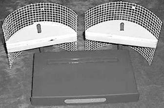
We needed a parabolic reflector to focus coverage. This design can reduce signal from some areas while enhancing signal in other areas. The reflector was designed to be installed in outdoor enclosures with WAP-11 access points, but it is becoming quite popular with people building indoor LANs, as well as with people building short point-to-point links. This design offers high performance and easy construction: scissors, tape, cardboard, tin foil, and 20 minutes, and you are in business. The completed project is shown in Figure 6-1.
Figure 6-1. Reflector installs without any pigtails
This antenna is so easy to make, tune, and install, and it performs so well, that you should try one before electing to purchase a commercial antenna. One benefit is that you can cheaply check to see whether you are purchasing enough commercial antenna gain to make the link you want.
Here are some advantages over other antennas:
- No pigtail [Appendix B] required
- No modification to AP (no voiding of warranty)
- No matching (SWR) problems
- No purchased parts
- Trivially easy construction
- Very low probability of error
- As good as or better performance than the Pringles can antenna [Hack #85]
- Superior front-to-back/front-to-rear ratio
- Improves wireless LAN privacy
- Reduces interference
This design can easily complete links up to one kilometer by sitting two WAP-11s in windows at each end of a link with clean line of sight. The 6-inch version of the antenna gives you about 10 to 12 dB of gain over the stock antenna. With a WAP11, this equates to approximately 27 to 33 dB of Effective Isotropically Radiated Power (EIRP). This means you wind up with an apparent power in the favored direction between 500 mW and 2 watts.
Of course, that gain has to come from somewhere. It comes from the back side of the reflector, so power that is normally transmitted in that direction is bounced forward. That feature of this antenna can be used to enhance the privacy of your wireless network, which was my reason for designing it in the first place. The rest is just gravy (but it is real and rather tasty gravy). Figure 6-2 shows the approximate radiation pattern of a 9-inch reflector.
To build this reflector, you can use the sample template in Figure 6-3 or download the original reflector template from http://www.freeantennas.com/projects/template/parabolic.pdf. The drawing can be scaled using a copy machine to make a dish of any reasonable size. The gain computations for various sizes of the dish are also provided on the web site, as well as rough graphs showing beam width and gain/frequency. This reflector is frequency independent, meaning it works with any wireless gear, on any band.
The square drawn on the diagram will help you to ensure that your scaling does not corrupt the aspect ratio of the template. In other words, if the square is still square after you enlarge or reduce the template, you still have a good template.
Figure 6-2. Approximate radiation pattern for a 9" reflector
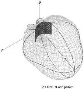
Figure 6-3. Reflector template
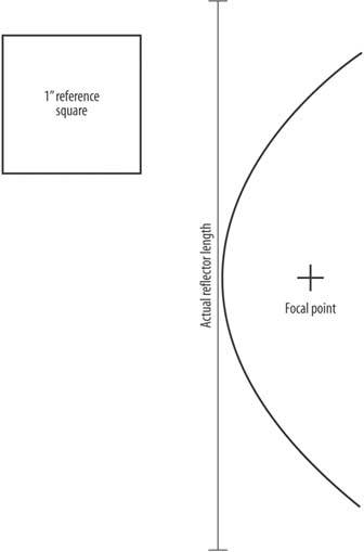
Focal length varies proportionally with the size of the dish, so the focal point is also shown in the drawings. Positioning of the feed point (focal point) is the most critical aspect of a deep dish parabolic. Errors of 1/4" or more are unacceptable at these frequencies. It might help to fiddle with the positioning, as small irregularities (~1/4" or greater) will move the focal point slightly. If the dipole is not in the focal point, you will lose gain. Parabolic reflectors also lose gain if your finished reflector varies much from the correct curve.
The reflector is designed to be fed by a dipole, which is why it is not circular. A dipole is long and cylindrical, while the focal point on a circular dish is circular. The focal point on this design is a cylinder. Many access points (such as the WAP-11) use one or more dipoles as their antenna. This reflector is the optimal shape for such an antenna. Some units, such as the WET-11, do not use dipoles as their antenna. You can download a modified template for the WET-11 at http://www.freeantennas.com/projects/template/index.html.
The reflector should be made from a piece of square material to shape the curve. If you need to reduce height for packaging reasons, a shorter antenna will work but will lose roughly 3 dB for each halving of reflector height. It is also important to try to get the dipole lined up in the center of the reflector.
Front-to-back ratio is a measurement of how well a directional antenna rejects interference from directions other than the desired direction. The front-to-back ratio with this antenna depends upon the size of the wire mesh you use to make the antenna. Finer mesh yields only slightly better gain but yields much better front-to-back ratio. Modeling shows the F/B ratio to be better than ~25 dB if you use 1/4" or smaller mesh. My calculated gain figures presume the reflector is 55 percent efficient. If you use a solid sheet of aluminum or copper as your reflector, your gain figures may be a little bit higher than these. The radiation pattern is narrower in the vertical plane than the horizontal plane.
People have made good reflectors from Pringles cans, large tin cans, wire screen, aluminum sheet, and tin roofing material. Any flat metal surface or screen, such as tinfoil taped to cardboard, will work. You can build one of these in less than a half an hour using an old shoebox and a roll of tin foil.
Michael Erskine
Bluetooth, Mobile Phones, and GPS
- Hacks 122: Introduction
- Hack 1. Set Up Bluetooth on Linux
- Hack 2. Set Up Bluetooth on Windows XP
- Hack 3. Connect Mac OS X with a Bluetooth Phone
- Hack 4. Connect Linux with a Bluetooth Phone
- Hack 5. Connect Windows XP with a Bluetooth Phone
- Hack 6. Use Your Treo as a Modem
- Hack 7. Send SMS from a PowerBook
- Hack 8. Remote Control Mac OS X with Bluetooth Phones and PDAs
- Hack 9. Remote Control Linux with a Bluetooth Phone
- Hack 10. Control XMMS with Bluetooth
- Hack 11. Liven Up Parties with a Participatory Slideshow
- Hack 12. Send SMS from Linux
- Hack 13. Remote Control Windows with Bluetooth Phones and PDAs
- Hack 14. Control Your Bluetooth Phone with FMA
- Hack 15. Control Your Computer from Your Palm
- Hack 16. Control Your Home Theater from Your Palm
- Hack 17. Choose a Cellular Data Plan
- Hack 18. Blog from Your Mobile Phone
- Hack 19. Get Google Maps on Your Mobile Phone
- Hack 20. Share Your GPS
- Hack 21. Broadcast Your GPS Position
- Hack 22. Map Wi-Fi Networks with Kismet and GPSd
Network Discovery and Monitoring
- Hacks 2339: Introduction
- Hack 23. Find All Available Wireless Networks
- Hack 24. Discover Networks with NetStumbler
- Hack 25. Detect Networks with Handheld PCs
- Hack 26. Find and Join Wireless Networks with AP Radar
- Hack 27. Detect Networks on Mac OS X
- Hack 28. Scan Passively with KisMAC
- Hack 29. Detect Networks with Kismet
- Hack 30. Monitor Wireless Links in Linux with Wavemon
- Hack 31. Analyze Traffic with Ethereal
- Hack 32. Track 802.11 Frames in Ethereal
- Hack 33. Watch Network Traffic
- Hack 34. grep Your Network
- Hack 35. Check Wi-Fi Network Performance with Qcheck
- Hack 36. Estimate Network Performance
- Hack 37. Get Real-Time Network Stats
- Hack 38. Graph Your Wireless Performance
- Hack 39. Find Radio Manufacturers by MAC
Wireless Security
- Hacks 4051: Introduction
- Hack 40. Stop Moochers from Stealing Your Wi-Fi Bandwidth
- Hack 41. Visualize a Network
- Hack 42. Secure Your Linux Network with WPA
- Hack 43. Control Wireless Access by MAC
- Hack 44. Authenticate Wireless Users
- Hack 45. Forward Ports over SSH
- Hack 46. Proxy Web Traffic over SSH
- Hack 47. Securely Connect Two Networks
- Hack 48. Generate a Tunnel Configuration Automatically
- Hack 49. Poll Wireless Clients
- Hack 50. Interrogate the Network
- Hack 51. Track Wireless Users
Hardware Hacks
- Hacks 5262: Introduction
- Hack 52. Add an External Antenna
- Hack 53. Do-It-Yourself Access Point Hardware
- Hack 54. Boot from a Compact Flash Hard Drive
- Hack 55. Increase the Range of a PowerBook
- Hack 56. Send Power over Your Ethernet
- Hack 57. The NoCat Night Light
- Hack 58. Upgrade the Linksys WET11
- Hack 59. Scan for Wireless Networks Automatically
- Hack 60. Backlight Your Zipit
- Hack 61. Unwire Your Pistol Mouse
- Hack 62. Mobilize Your WRT54G with the WiFiCar
Software Hacks
- Hacks 6382: Introduction
- Hack 63. Build Your Own Access Point with Linux
- Hack 64. Bridge Your Linux AP
- Hack 65. Protect Your Bridge with a Firewall
- Hack 66. Filter MAC with HostAP and Madwifi
- Hack 67. Upgrade Your Wireless Router
- Hack 68. Set Up an OLSR Mesh Network
- Hack 69. Extend Your Wireless Network with WDS
- Hack 70. Pebble
- Hack 71. Wall Off Your Wireless
- Hack 72. Run Your Mac as an Access Point
- Hack 73. Run Linux on the Zipit Wireless Messenger
- Hack 74. Capture Wireless Users with NoCatAuth
- Hack 75. Capture Wireless Users on a Small Scale
- Hack 76. Build an Online Community in Your Offline Neighborhood
- Hack 77. Manage Multiple AirPort Base Stations
- Hack 78. Advertise Bonjour Services in Linux
- Hack 79. Advertise Any Service with Bonjour in Mac OS X
- Hack 80. Redirect Brought to you by Bonjour Ads
- Hack 81. Use a Windows-Only Wireless Card in Linux
- Hack 82. Use Your Orinoco Card with Hermes AP
Do-It-Yourself Antennas
- Hacks 8393: Introduction
- Hack 83. Make a Deep Dish Cylindrical Parabolic Reflector
- Hack 84. Spider Omni Antenna
- Hack 85. Pringles Can Waveguide
- Hack 86. Pirouette Can Waveguide
- Hack 87. Primestar Dish with Waveguide Feed
- Hack 88. Primestar Dish with Biquad Feed
- Hack 89. Cut a Cable Omni Antenna
- Hack 90. Build a Slotted Waveguide Antenna
- Hack 91. The Passive Repeater
- Hack 92. Determine Your Antenna Gain
- Hack 93. Build Cheap, Effective Roof Mounts
Wireless Network Design
- Hacks 94100: Introduction
- Hack 94. Analyze Elevation Profiles for Better Long-Range Wireless Networking
- Hack 95. Build a Wireless Network for the Large House
- Hack 96. Establish Line of Sight
- Hack 97. Calculate the Link Budget
- Hack 98. Align Antennas at Long Distances
- Hack 99. Slow Down to Speed Up
- Hack 100. Take Advantage of Antenna Polarization
Appendix A. Wireless Standards
- Appendix A. Wireless Standards
- Section A.1. 802.11: The Mother of All IEEE Wireless Ethernet
- Section A.2. 802.11a: The Betamax of the 802.11 Family
- Section A.3. 802.11b: The De Facto Standard
- Section A.4. 802.11g: Like 802.11b, only Faster
- Section A.5. 802.16: WiMAX Long Distance Wireless Infrastructure
- Section A.6. Bluetooth: Cable Replacement for Devices
- Section A.7. 900 MHz: Low Speed, Better Coverage
- Section A.8. CDPD, 1xRTT, and GPRS: Cellular Data Networks
- Section A.9. FRS and GMRS: Super Walkie-Talkies
- Section A.10. 802.1x: Port Security for Network Communications
- Section A.11. WPA & 802.11i
- Section A.12. BSS Versus IBSS
Appendix B. Wireless Hardware Guide
EAN: 2147483647
Pages: 178
