3.6 Diagrams
3.6 Diagrams
UML diagrams are where it all comes together. As I already mentioned, in the UML there is no formal way of bounding or containing a diagram (that is, no notation for the diagram itself), so there are no relationships between diagrams. Instead, diagrams are the graphical presentation vehicles for aspects of a model. They don't stand alone, but are meant to be part of the textual narrative that provides the model specification.
The UML specifically includes nine different diagrams in its documentation, which I'll discuss briefly here. However, these diagram types are process-dependent and suggestive, rather than prescriptive. The UML allows the modeler to combine any and all elements into diagrams, depending on the modeling needs at hand. In practice, of course, only certain combinations of elements are sensible, and these nine types are pretty much the "canonical" ones for object-oriented programming.
However, all of this really needs to be considered in the context of the process and the tool being used. Although the RUP includes all of these diagrams, D'Souza and Wills' book (for example) doesn't.
Detailing these diagrams and the alternatives can be a book by itself. Most of the literature on the UML focuses on these diagrams, so there are already many good books to choose from. Because this book is as process-independent as the UML, I'll leave detailed discussions of these diagrams to the many other more programming-oriented, books out there and to come.
3.6.1 Class Diagram
For traditional object-oriented development, the class diagram is the keystone for the system model. In UML terms, it is a view of the static structural model. It is not a formal partitioning of the model; therefore, individual class diagrams "do not represent divisions in the underlying model" (Rational Software Corporation 1999, 3-33).
Aside from classes, a class diagram can also contain interfaces, packages, relationships, and instances (such as objects and links). The UML Specification suggests that "a better name would be static structural diagram," but bows to tradition and brevity in sticking with class diagram (1999).
The UML recognizes the distinction between class and type; the nature of what is meant by class changes conceptually, depending on the development stage that the modeling effort is in. For those interested, Martin Fowler, Kendall Scott, and Ivar Jacobson do an admirable job of capturing and explaining the modeling nuances of class, type and object in UML Distilled: Applying the Standard Object Modeling Language (Fowler, Scott, and Jacobson 1997).
3.6.2 Use Case Diagram
For use case-driven development, the use case diagram is the keystone of the modeling effort. Use case diagrams show actors and use cases, together with their relationships. These include the following:
Associations between the actors and the use cases
Generalizations between the actors
Generalizations, extends, and includes relationships among the use cases
The use cases may be enclosed by a rectangle to show the boundary of the containing system, and so on. As will be evident in the UML patterns, use case diagrams by themselves are essentially trivial. The real substance of a use case is in the text (narrative).
A use case captures the significant parts of an interaction with the system or some part of the system by the actor(s) defining the scope, context, and requirements. Use cases can be used in a variety of ways throughout the development effort (for example, as the basis for setting up the test environment and as a starting point for a user manual).
The following is an example of a basic use case, which describes making a phone call, in text format first and then the diagram (see Figure 3.29). The caller initiates the use case, and the receiver is a secondary actor. The system that the caller and actor interact with is, of course, the phone system. The alternate flows aren't completely described, but indicate the kind of conditions that alternate flows handle.
Figure 3.29. Telephone call use case diagram.
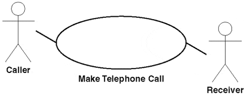
Actors:
Caller
Receiver
Normal Flow:
The use case begins when Caller picks up the handset of telephone.
Caller listens for dial tone.
(Alternate flow: no dial tone)
Caller dials a phone number.
Phone System rings Receiver's phone.
(Alternate flow: Wrong number)
Receiver answers.
(Alternate flow: no answer)
Caller conducts conversation.
The use case ends when Caller hangs up phone.
Alternate Flows:
No dial tone
Wrong number
No answer
3.6.3 Interaction Diagrams
Interaction diagrams are used in the dynamic modeling of the system. There are two kinds: sequence diagrams and collaboration diagrams.
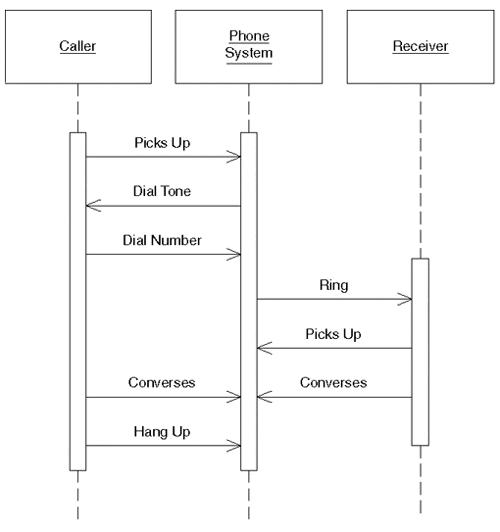
Sequence Diagram
A sequence diagram shows an interaction arranged in time sequence: the objects (not classes) and the messages that pass between them when an interaction occurs. These are what Ivar Jacobson used to call interaction diagrams.
A sequence diagram has a list of participating objects across its top, shown as rectangles. Each object rectangle contains at least a name, always underlined to indicate that the rectangle is an object and not a class. Below each object rectangle, shown with a dotted line, is the object lifeline, the time-ordered visual framework for message exchanges between the objects (and with the system). A narrow vertical rectangle called the activation represents the period of time an object is actually performing an action (directly or through an intermediary, such as another object). Object messages appear as arrows with a text description. Figure 3.30 shows the basic elements of a sequence diagram.
Figure 3.30. Simple sequence diagram.
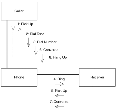
Collaboration Diagram
A collaboration diagram also shows the passing of messages between objects, but focuses on the objects and messages and their order instead of the time sequence. The sequence of interactions and the concurrent threads are identified using sequence numbers. A collaboration diagram shows an interaction organized around the roles in the interaction and their links to each other, and shows the relationships among the objects playing the different roles. The UML Specification suggests that collaboration diagrams are better for real-time specifications and for complex scenarios than sequence diagrams.
Figure 3.31 shows the telephone call example expressed as a collaboration diagram.
Figure 3.31. Collaboration diagram showing static structure of objects and messages flowing between them.
3.6.4 State Diagrams
State diagrams show the states, events, transitions, and activities for the system, depicted as state machines. They're part of dynamic modeling rather than structural modeling. They are used to describe the behavior of a model element such as an object or an interaction, describing "possible sequences of states and actions through which the element can proceed during its lifetime as a result of reacting to discrete events (for example, signals, operation invocations)" (Rational Software Corporation 1999, 3-131).
The official name in the UML is statechart diagram, but state diagram pops up all over the place in the UML Specification and in much of the literature. The term statechart reflects its origins in Harel Statecharts, a long-used tool for modeling real-time systems, which the UML has modified to fit object-oriented development.
A state diagram is typically used to model the behavior of an object that needs a complete description of its discrete states. Many objects in standard business systems may not have significant states, in which case they will not need state diagrams. (On the other hand, for those developing real-time systems, a discussion of state diagrams and state modeling can be a book by itself.) A state diagram is typically associated with one and only one class, and lists all the states that a particular object can have during system operation.
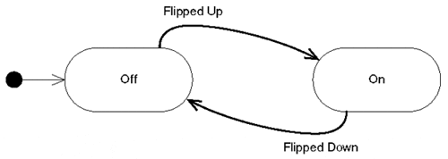
Each rounded rectangle represents one state that an object can be in. A state diagram must represent all the states in which an object can find itself, as well as define an initial state the object will be in. An initial state is shown as a filled-in black circle. The final state of an object is not required if the object has nofinal state, such as in a system that is always running.
An object passes from one state to another following a transition triggered by an event within the system (typically, a method invocation). A transition is shown by drawing an arrow from one state to another and is associated with an event that triggers the transition.
Figure 3.32 shows the state diagram for a light switch that shows both transition lines and events.
Figure 3.32. State diagram showing the two states of a light switch.
3.6.5 Activity Diagrams
An activity diagram is a "special case of a state diagram in which all (or at least most) of the states are action or subactivity states and in which all (or at least most) of the transitions are triggered by completion of the actions or subactivities in the source states" (Rational Software Corporation 1999, 3-151). In fact, they're basically sophisticated versions of flowcharts. They're intended to cover workflows and processes, and have much of the flavor of flowcharts without the negative "baggage." Their depiction as versions of state diagrams is subject to much criticism, but at least it helps to make them a consistent member of the UML family.
An activity diagram is attached to a class (which includes a use case for the UML), to a package, or to the implementation of an operation. The UML Specification says that they "focus on flows driven by internal processing (as opposed to external events)" (1999, 3-151). It recommends using them where the events involved represent the completion of internally generated actions (for procedural flow of control).
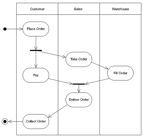
In an activity diagram, swimlanes are used to package the organizational boundaries within an activity model: they are used to show who is doing what in an activity model.
When it is necessary to indicate that two or more actions occur in parallel, a line called a synchronization bar shows where each thread in the parallel actions halts, waiting until the other threads reach the same point.
Figure 3.33 shows an activity model for the workflow of an order system. Organized around the responsibilities of the customer, sales, and the warehouse, swimlanes are the vertical lines partitioning the diagram and identifying the responsibilities for each activity.
Figure 3.33. An order process with three swimlanes, each showing the responsibility of the business unit during the process.
3.6.6 Implementation Diagrams
Implementation diagrams model implementation artifacts and considerations, including how the source code is structured and how (and where) the executables are made available. The UML Specification suggests that they also can be applied in a broader sense to business modeling. Components are the business procedures and documents, and the run-time structure is the organization units and resources (human and other) of the business (1999, 3-165). There are two types of implementation diagrams: component diagrams and deployment diagrams.
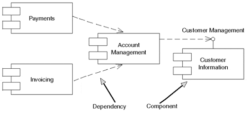
Component Diagrams
Component diagrams show the structure of the code (see Figure 3.34). According to the UML Specification, they are "the dependencies among software components, including source code components, binary code components, and executable components" (1999). The nuances of component are such that it seems to be as malleable a term as architecture and abstraction.
Figure 3.34. Component diagram showing the dependencies between components of a payment-processing system
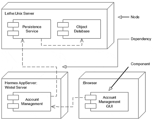
Deployment Diagrams
Deployment diagrams show the structure of the runtime system(see Figure 3.35), including the "configuration of runtime processing elements and the software components, processes, and objects that live on them" (Rational Software Corporation 1999, 3-166). For business modeling, the UML Specification says runtime elements include workers and organizational units, and the software components include procedures and documents used by the workers and organizational units.
Figure 3.35. Deployment diagram showing run-time nodes and components for a browser-based three-tier account management system
EAN: 2147483647
Pages: 100