Converting Shapes and CAD Symbols into Components
3 4
Process engineering shapes don't work like other Visio shapes. They have categories, tag formats, and other attributes that make your diagram more valuable. However, you may need to create your own shapes or modify existing Visio shapes to complete your diagram. To take full advantage of the Visio Professional Process Engineering solution, you can convert other Visio shapes or even CAD symbols (from an AutoCAD .dwg or .dxf file) to process engineering shapes so that they will appear in your model. The Shape Conversion command on the Process Engineering menu applies the necessary component information to any shape or symbol, as Figure 27-32 shows.
The results of the conversion vary depending on the source of the shapes:
- Shapes on the drawing page. If you convert selected shapes on the page, Visio applies a category, custom properties, and tags to each shape so that it appears in the appropriate model windows. Each shape is linked to a new master on the document stencil.
- Shapes from a stencil. If you convert an existing stencil, all the master shapes are updated with a category, custom properties, and tags. When you drag a converted shape from the stencil onto the drawing page, it appears in all the appropriate model windows.
- Shapes from an AutoCAD file. If you convert the symbols from a .dwg or .dxf file, Visio creates a new stencil and adds a master shape for each converted symbol with the appropriate category, custom property, and tag information. To save the new stencil, click its title bar, and then choose File, Save.
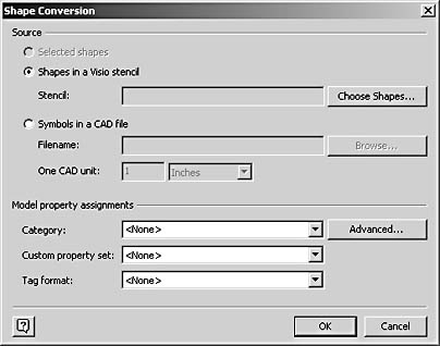
Figure 27-32. You can convert shapes from other sources, including AutoCAD files, to process engineering components with the Shape Conversion command.
To convert shapes into process engineering shapes, follow these steps:
- If you're converting individual shapes on the drawing page, select the shapes.
- Choose Process Engineering, Shape Conversion.
- Under Source, select one of the following:
- If you're converting shapes on the Visio drawing page, choose the Selected Shapes option.
- If you're converting shapes on a Visio stencil, choose the Shapes In A Visio Stencil option, and then click Choose Shapes. Select the stencil, select the shapes you want to convert, and then click OK.
Tip
To convert the shapes on the current diagram's document stencil—that is, all the shapes based on master shapes that you've added to a diagram—in the Choose Shapes dialog box, select the name of the file in the Documents list. - If you're converting AutoCAD symbols, choose the Symbols In A CAD File option. Type the name and path of the CAD file in the Filename box, or click Browse to locate an AutoCAD file. In the One CAD Unit boxes, indicate the units of measure that you want to use. This setting establishes the drawing scale in Visio.
- In the Category list, select a category for the converted shapes.
Note
All the selected shapes will be assigned to the same category unless you click the Advanced button and specify different categories for individual shapes. - In the Custom Property Set list, select a custom property set for the converted shapes. All the custom properties in the set will be added to each of the selected shapes.
- In the Tag Format list, select the tag format to use in labeling the converted shapes.
- Click OK to start the conversion. Visio converts the shape on the drawing page or on a stencil. If you converted CAD symbols, they are added as a new stencil of master shapes.
Note
If you convert a stencil or CAD symbols, make sure to save the changes to the master shapes on the stencil. To do this, right-click a stencil title bar, and then choose Save or Save As.
Troubleshooting
An equipment shape in a P&ID or PFD no longer works—its tag and other information have been deleted.
Some operations in Visio can cause a process engineering shape to lose its data- tracking attributes, and you must use the Shape Conversion command to reapply the lost functionality. For example, if you ungroup a grouped shape, or use a shape operation command (choose Shape, Operations) with process engineering shapes, Visio discards the shape's custom property, tag, and category information. You can reapply the information by converting the shape.
EAN: 2147483647
Pages: 211