Labeling, Tagging, and Numbering Components
3 4
Each component can include an identifying tag, which can be hidden or customized. In addition, component shapes can include properties that store real-world data, such as a component's temperature rating or the line size of a pipeline, as Figure 27-26 shows. You can display custom property data on the drawing page as part of a component's tag or as a custom text label called a callout shape.
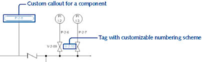
Figure 27-26. You can use intelligent callout shapes to label the components in your diagram.
Labeling Shapes with Component Data
When you associate a callout shape with a component, you can specify the value to use as a label, as Figure 27-27 shows. Visio updates the callout's label if you edit the component's properties.
Follow these steps to set up a callout:
- Drag a custom callout shape from the Process Annotations stencil onto the drawing page.
- Drag the callout shape's control handle to any point on the shape whose data you want to display.
- In the Configure Callout dialog box, select the custom properties you want to display in the callout shape.
- To display more than one custom property, select the check boxes you want. To change the order that properties appear on the callout shape, select a property and click Move Up or Move Down.
- If you are displaying more than one custom property in the callout shape, separate the values to ensure that they're readable. To do this, select an option from the Separator list. (The Separator option is not available if you display only one custom property.)
- Click OK.
Tip
You can change the settings for a callout shape any time by right-clicking it, choosing Configure Callout, and selecting different custom properties.
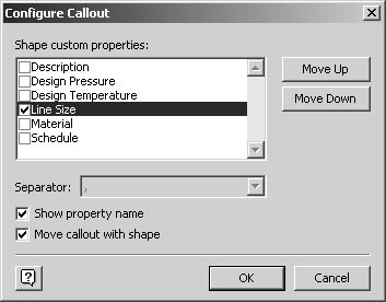
Figure 27-27. You can display component information using custom callout shapes on the Process Annotations stencil.
You can also display information about a shape directly in the shape's tag, or label. By default, the shape's tag is displayed. You can hide it by right-clicking the shape and choosing Hide Tag; and you can show it by right-clicking the shape and choosing Show Tag. For details about setting up a tag format to display the values for specific properties, see the next section, "Tagging Components."
Tagging Components
Each component has a unique tag that Visio Professional uses to identify and track it. When you first drag a shape to the drawing page, Visio labels it with a unique component tag based on the tag format associated with the master shape. If there are multiple shapes associated with a component, each of those shapes has the same tag. For example, when you drop a valve on a pipeline, the pipe is split into two shapes, one on either side of the valve, but both pipe segments have the same tag. This ensures that the correct information is listed for each of the shapes when one of the shapes is updated.
By default, the component tag is composed of the tag name and a one-digit counter. So, for example, if you drag a pump shape onto a new drawing, the pump is tagged Pump-1. If you drag another pump onto the page, it is tagged Pump-2.
You can change the tag for a shape by editing the shape's text manually, which isn't a particularly efficient method of tagging large numbers of components. Visio provides a more efficient way to write tags quickly and consistently. You can apply a tag format to shapes. The tag format, composed of alphanumeric text and component data, provides the rules that Visio Professional follows when tagging a component. And if the existing tag formats don't meet your needs, you can customize them.
You can apply a tag format to an individual shape, multiple selected shapes, or a master on a stencil, including the document stencil, which is the quickest way to update all the shapes in a drawing.
To apply a tag format to one or more shapes on the drawing page, follow these steps:
- Select the shapes you want to tag by doing one of the following:
- To tag specific shapes in the diagram, select the shapes you want.
Tip
Press Shift+click to select multiple shapes. - To tag all the components that are represented by the same shape—for example, all the gate valves—don't select anything.
- To tag specific shapes in the diagram, select the shapes you want.
- Choose Process Engineering, Apply Tag Format.
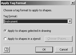
- In the Tag Format list, select the tag format you want to apply.
- Do one of the following:
- If you're applying the format to selected shapes, select the Apply To Shapes Selected In Drawing option, and then click OK to complete the task and apply the new tag format.
- If you're applying the format to all the components represented by a particular shape, select the Apply To Shapes In A Stencil option, and then click Choose Shapes.
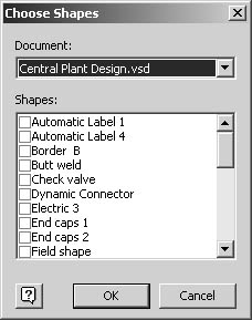
- In the Shapes list, select the component shapes you want to apply the format to. Shapes are listed in alphabetical order by the name of the master shape that represents them. Click OK.
- In the Apply Tag Format dialog box, click OK to apply the new format.
Defining Component Tags
To customize the tagging scheme used in your diagram, you can create and edit the tag format Visio applies to component shapes. Tags can be pretty smart—you can display the value of custom properties in a tag, automatically number component tags in sequence, and display more than one line of information. With the Edit Tag Formats command on the Process Engineering menu, you can revise the format used for existing tags, as Figure 27-28 shows. Or you can create a new tag format, which you can apply to shapes with the Apply Tag Format command.
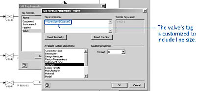
Figure 27-28. You can use the Edit Tag Formats command to customize the appearance of tags.
The format for a tag is based on a tag expression, which is similar to the Visio text fields that insert file information. A tag expression can include punctuation and fields that are set off in square brackets ([ ]) as you can see in Figure 27-28. Visio evaluates the value of the field to display the tag on the shape. For example, if a tag expression includes the custom property Line Size, Visio inserts the value for the shape's Line Size custom property. If you haven't entered a value for Line Size, the tag displays nothing.
To number components, you can add a counter to a tag expression. Visio increments the counter field in one of two ways:
- If you select shapes and then define a tag expression with a counter, the selected shapes are numbered according to their stacking order (the order you added them to the page).
- If no shapes are selected, Visio numbers shapes as you add them.
By default, a counter includes only one digit, but you can specify two or more digits. Visio inserts leading zeros to fill the number of digits you specify. For example, if you specify two digits, the first pump in a diagram is labeled Pump - 01 and the hundredth pump is labeled Pump - 100.
To delete or rename an existing tag format, choose Process Engineering, Edit Tag Formats, which opens the Edit Tag Formats dialog box, as Figure 27-29 shows. Select the tag format, and then click Delete or Rename. If you're renaming the tag format, type a new name and then click elsewhere in the dialog box. Click OK to close the dialog box.
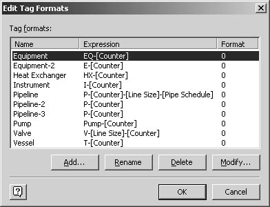
Figure 27-29. To revise or create a tag format, use the Edit Tag Formats command on the Process Engineering menu.
Follow these steps to create a new tag format:
- Choose Process Engineering, Edit Tag Formats to display the Edit Tag Formats dialog box, and then click Add.
- In the Name box, type a name for the new tag format as you want to identify it in the Apply Tag Formats dialog box.
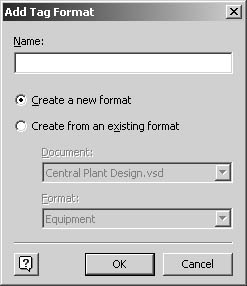
- Do one of the following:
- To base the new tag format on the default tag format, select the Create A New Format option.
- To base the new tag format on an existing format, select the Create From An Existing Format option. Then, from the Document list, select the document or stencil that contains the existing tag format you want to use. The tag formats included in that document or stencil are listed. From the Format list, select the tag format you want to base the new tag format on.
- Click OK to return to the Edit Tag Formats dialog box.
- In the Tag Formats list, select the tag you just added, and then click Modify to display the Tag Format Properties dialog box.
- In the Tag Expression box, type or edit the text to change any letters or punctuation that appears.
Tip
To create a tag that has more than one line, click to place the insertion point in the tag expression, and then press the Enter key. - To insert a custom property in the tag, click in the tag expression where you want to insert the field, select a custom property in the Available Custom Properties list, and then click Insert Property. Visio inserts a field enclosed in square brackets. For example, [Material].
- To specify the number of leading zeros for a counter, select an option in the Format list.
- When the tag expression is formatted the way you want, click OK to return to the Edit Tag Formats dialog box, and then click OK.
Tip
You can also create and apply tag formats to process engineering shapes by using the Component Model Properties dialog box.
Renumbering Components
To help you distinguish one pump or valve from another, Visio assigns each component a number when it's added to the diagram. For example, the first pump you drag to the page is tagged Pump-1, and the second is Pump-2. You can change the way components are numbered automatically with the Renumber Components command, as Figure 27-30 shows. Tag numbers are incremented as you add shapes, and the format of the number itself is determined by the tag format as described in the previous section. But if you've deleted components or want to count different kinds of components separately, Visio can renumber component shapes based on criteria that you provide. After you renumber components, new component shapes are numbered incrementally where the last component numbers left off.
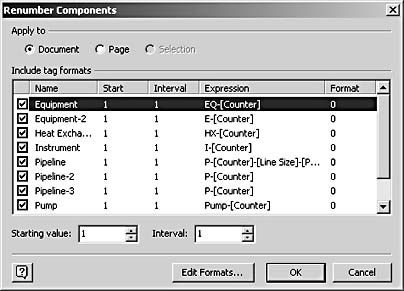
Figure 27-30. You can specify how you want Visio to renumber component shapes.
Follow these steps to renumber components:
- Select specific components you want to change or cancel all selections to renumber all shapes, and then choose Process Engineering, Renumber Components.
- Under Apply To, select an option. You can renumber all components in the entire drawing file (Document), just those on the currently displayed page (Page), or selected shapes only (Selection).
- To limit the renumbering to shapes that use a particular tag format, such as pumps or valves, under Include Tag Formats, clear the tag formats you don't want to include. By default, all tag formats are selected, which means that all tags that include a counter will be renumbered.
- In the Starting Value box, type or select the first number to start counting with.
- In the Interval box, type or select a number by which the counter is incremented.
- Click OK to reset the counter in the component tags.
Note
To prevent Visio from automatically numbering components you add, choose Process Engineering, Diagram Options, and clear the Number Components When They Are Added To The Drawing check box.
EAN: 2147483647
Pages: 211