Operation of RIP
| Note The metric for RIP is hop count. The RIP process operates from UDP port 520; all RIP messages are encapsulated in a UDP segment with both the Source and Destination Port fields set to that value. RIP defines two message types: Request messages and Response messages. A Request message is used to ask neighboring routers to send an update. A Response message carries the update. The metric used by RIP is hop count, with 1 signifying a directly connected network of the advertising router and 16 signifying an unreachable network. On startup, RIP broadcasts a packet carrying a Request message out each RIP-enabled interface. The RIP process then enters a loop, listening for RIP Request or Response messages from other routers. Neighbors receiving the Request send a Response containing their routing table. When the requesting router receives the Response messages, it processes the enclosed information. If a particular route entry included in the update is new, it is entered into the routing table along with the address of the advertising router, which is read from the source address field of the update packet. If the route is for a network that is already in the table, the existing entry will be replaced only if the new route has a lower hop count. If the advertised hop count is higher than the recorded hop count and the update was originated by the recorded next -hop router, the route will be marked as unreachable for a specified holddown period. If at the end of that time the same neighbor is still advertising the higher hop count, the new metric will be accepted. [5]
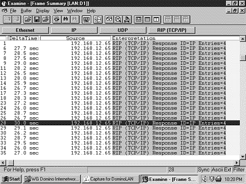
RIP Timers and Stability FeaturesAfter startup, the router gratuitously sends a Response message out every RIP-enabled interface every 30 seconds, on average. The Response message, or update, contains the router's full routing table with the exception of entries suppressed by the split horizon rule. The update timer initiating this periodic update includes a random variable to prevent table synchronization. [6] As a result, the time between individual updates from a typical RIP process may be from 25 to 35 seconds. The specific random variable used by Cisco IOS, RIP_JITTER, subtracts up to 15% (4.5 seconds) from the update time. Therefore, updates from Cisco routers vary between 25.5 and 30 seconds (Figure 5.1). The destination address of the update is the all- hosts broadcast 255.255.255.255. [7]
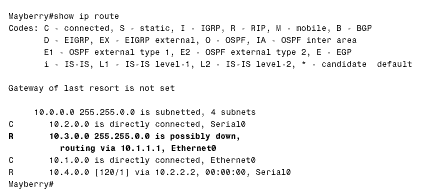
Figure 5.1. RIP adds a small random variable to the update timer at each reset to help avoid routing table synchronization. The RIP updates from Cisco routers vary from 25.5 to 30 seconds, as shown in the delta times of these updates. Several other timers are employed by RIP. Recall from Chapter 4, "Dynamic Routing Protocols," the invalidation timer, which distance vector protocols use to limit the amount of time a route can stay in a routing table without being updated. RIP calls this timer the expiration timer, or timeout . Cisco's IOS calls it the invalid timer. The expiration timer is initialized to 180 seconds whenever a new route is established and is reset to the initial value whenever an update is heard for that route. If an update for a route is not heard within that 180 seconds (six update periods), the hop count for the route is changed to 16, marking the route as unreachable. Another timer, the garbage collection or flush timer, is set to 240 seconds “60 seconds longer than the expiration time. [8] The route will be advertised with the unreachable metric until the garbage collection timer expires , at which time the route is removed from the routing table. Figure 5.2 shows a routing table in which a route has been marked as unreachable, but has not yet been flushed.
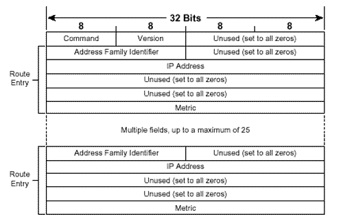
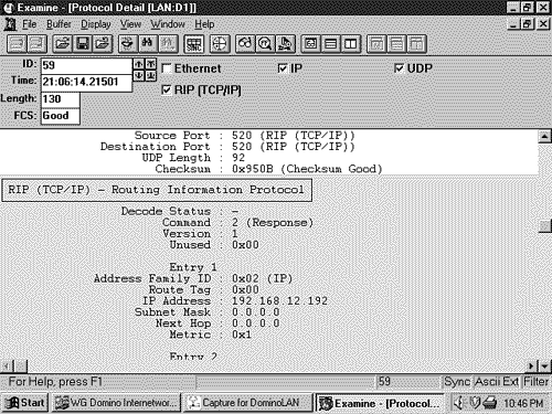
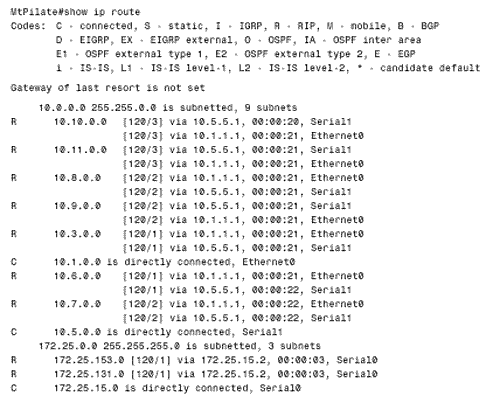
Figure 5.2. This router has not heard an update for subnet 10.3.0.0 for more than six update periods. The route has been marked unreachable, but has not yet been flushed from the routing table. The third timer is the holddown timer. Although RFC 1058 does not call for the use of holddowns, Cisco's implementation of RIP does use them. An update with a hop count higher than the metric recorded in the routing table will cause the route to go into holddown for 180 seconds (again, three update periods). These four timers can be manipulated with the command: timers basic update invalid holddown flush This command applies to the entire RIP process. If the timing of one router is changed, the timing of all the routers in the RIP domain must be changed. Therefore, these timers should not be changed from their default values without a specific, carefully considered reason. RIP employs split horizon with poison reverse and triggered updates. A triggered update occurs whenever the metric for a route is changed and, unlike regularly scheduled updates, may include only the entry or entries that changed. Also unlike regular updates, a triggered update does not cause the receiving router to reset its update timer; if it did, a topology change could cause many routers to reset at the same time and thus cause the periodic updates to become synchronized. To avoid a " storm " of triggered updates after a topology change, another timer is employed. When a triggered update is transmitted, this timer is randomly set between 1 and 5 seconds; subsequent triggered updates cannot be sent until the timer expires. Note Silent hosts Some hosts may employ RIP in a "silent" mode. These so-called silent hosts do not generate RIP updates, but listen for them and update their internal routing tables accordingly . As an example, using routed with the -q option enables RIP in silent mode on a UNIX host. RIP Message FormatThe RIP message format is shown in Figure 5.3. Each message contains a command and a version number and can contain entries for up to 25 routes. Each route entry includes an address family identifier, the IP address reachable by the route, and the hop count for the route. If a router must send an update with more than 25 entries, multiple RIP messages must be produced. Note that the initial portion of the message is four octets, and each route entry is 20 octets. Therefore the maximum message size is 4 + (25 X 20) = 504 octets. Including an eight-byte UDP header will make the maximum RIP datagram size (not including the IP header) 512 octets. Figure 5.3. The RIP message format. Command will always be set to either one, signifying a Request message, or two, signifying a Response message. There are other commands, but they are all either obsolete or reserved for private use. Version will be set to one for RIPv1. Address Family Identifier is set to two for IP. The only exception to this is a request for a router's (or host's) full routing table, as discussed in the following section. IP Address is the address of the destination of the route. This entry may be a major network address, a subnet, or a host route. The section titled "Classful Route Lookups" examines how RIP distinguishes among these three types of entries. Metric is, as previously mentioned , a hop count between 1 and 16. An analyzer decode of a RIP message is shown in Figure 5.4. Figure 5.4. The protocol analyzer labels the fields that RIPv1 does not use as Subnet Mask and Next Hop. These fields are used by RIPv2 and are described in Chapter 7. Several historical influences contributed to the inelegant format of the RIP message in which far more bit spaces are unused than are used. These influences range from RIP's original development as an XNS protocol and the developer's intentions for it to adapt to a large set of address families to the influence of BSD, and its use of socket addresses to the need for fields to fall on 32-bit word boundaries. Request Message TypesA RIP Request message may request either a full routing table or information on specific routes only. In the former case, the Request message will have a single route entry in which the address family identifier is set to zero, the address is all zeros (0.0.0.0), and the metric is 16. A device receiving such a request responds by unicasting its full routing table to the requesting address, honoring such rules as split horizon and boundary summarization (discussed in "Classful Routing: A Summarization at Boundary Routers," later in this chapter). Some diagnostic processes may need to know information about a specific route or routes. In this case, a Request message may be sent with entries specifying the addresses in question. A device receiving this request will process the entries one-by-one, building a Response message from the Request message. If the device has an entry in its routing table corresponding to an address in the request, it will enter the metric of its own route entry into the metric field. If not, the metric field will be set to 16. The response will tell exactly what the router knows , with no consideration given to split horizon or boundary summarization. As noted previously, hosts may run RIP in silent mode. This approach allows them to keep their routing tables up-to-date by listening to RIP updates from routers without having to send RIP Response messages uselessly on the network. However, diagnostic processes may need to examine the routing table of these silent hosts. Therefore, RFC 1058 specifies that if a silent host receives a request from a UDP port other than the standard RIP port of 520, the host must send a response. Classful RoutingNote RIPv1 can perform equal-cost load balancing. The routing table in Figure 5.5 contains RIP-derived routes, which are recognized from the key to the left of each entry. Of significance in these entries are the bracketed tuples; as discussed in Chapter 3, "Static Routing," the first number is the administrative distance, and the second number is the metric. It is readily seen that RIP has an administrative distance of 120, and as already stated, the metric for RIP is hop count. Therefore, network 10.8.0.0 is 2 hops away, via either E0 or S1. If more than one route exists to the same destination with equal hop counts, equal-cost load balancing will be performed. The routing table of Figure 5.5 contains several multiple, equal-cost routes. Figure 5.5. This routing table contains subnets of networks 10.0.0.0 and 172.25.0.0. All networks not directly connected were derived by RIP. When a packet enters a RIP-speaking router and a route table lookup is performed, the various choices in the table are pruned until a single path remains. First, the network portion of the destination address is read and the routing table is consulted for a match. It is this first step of reading the major class A, B, or C network number that defines a classful routing table lookup. If there is no match for the major network, the packet is dropped and an ICMP Destination Unreachable message is sent to the packet's source. If there is a match for the network portion, the subnets listed for that network are examined. If a match can be found, the packet is routed. If a match cannot be made, the packet is dropped and a Destination Unreachable message is sent. Note Definition of a classful route lookup Classful Routing: Directly Connected SubnetsClassful route lookups can be illustrated with three examples (referring to Figure 5.5):
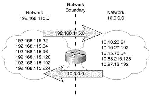
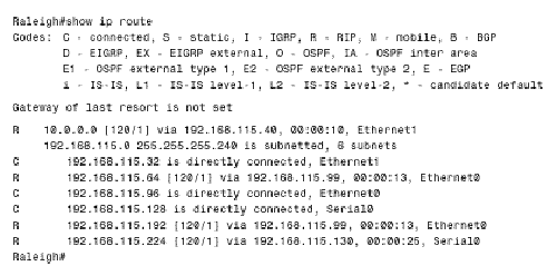
Another look at Figure 5.3 reveals that there is no provision for RIP to advertise a subnet mask along with each route entry. And accordingly, no masks are associated with the individual subnets in the routing table. Therefore, if the router whose forwarding database is depicted in Figure 5.5 receives a packet with a destination address of 172.25.131.23, there is no positive way to determine where the subnet bits end and the host bits begin, or even if the address is subnetted at all. The router's only recourse is to assume that the mask configured on one of its interfaces attached to 172.25.0.0 is used consistently throughout the internetwork. It will use its own mask for 172.25.0.0 to derive the subnet of the destination address. As the routing tables throughout this chapter illustrate , a router that is directly connected to a network will list the network in a heading along with the subnet mask of the connecting interface and will then list all the known subnets of the network. If the network is not directly connected, there is a listing only for the major-class network and no associated mask. Because the destination addresses of packets being routed by a classful routing protocol are interpreted according to the subnet masks locally configured on the router's interfaces, all subnet masks within a major, class-level network must be consistent. Classful Routing: Summarization at Boundary RoutersA question arises from the preceding discussion: How does a RIP process interpret the subnet of a major network if it has no interfaces attached to that network? Without an interface on the class A, B, or C network of the destination, the router has no way of knowing the correct subnet mask to use and therefore no way of correctly identifying the subnet. The solution is simple: If a router has no direct attachments to the network, then it needs only a single route entry pointing toward a router that is directly attached. Note Boundary routers perform route summarization, also known as subnet hiding. Figure 5.6 shows a router that is attached at the boundary of two major networks, the class A network 10.0.0.0 and the class C network 192.168.115.0. This boundary router does not send details of the subnets of one major network into the other major network. As the illustration shows, it automatically performs summarization, or subnet hiding . It advertises only the address 10.0.0.0 into network 192.168.115.0 and advertises only the address 192.168.115.0 into network 10.0.0.0. Figure 5.6. This router, at the boundary of two major networks, does not advertise the subnets of one network to routers within the other network. In this way, the routing tables for routers within network 192.168.115.0 have only a single entry that directs packets for 10.0.0.0 toward the boundary router. The boundary router has an interface directly on network 10.0.0.0 and therefore has a subnet mask with which to derive the subnet for routing a packet within that network's "cloud." Figure 5.7 shows what the routing table of a router within 192.168.115.0 would look like with a single, subnetless entry for 10.0.0.0. Figure 5.7. This router has a single entry pointing toward network 10.0.0.0. The next-hop address is the boundary router, since the network is recorded as being one hop away. Chapter 3's brief discussion of discontiguous subnets ”subnets of a major network address separated by a different major network ”notes that they present a problem for classful routing protocols such as RIP and IGRP. The problem occurs when discontiguous subnets are automatically summarized at network boundaries. A case study in the configuration section of this chapter demonstrates the problem and a solution. Classful Routing: SummaryThe defining characteristic of a classful routing protocol is that it does not advertise an address mask along with the advertised destination address. Therefore, a classful routing protocol must first match the major class A, B, or C network portion of a destination address. For every packet passing through the router:
|
