Content Switch Operational Modes
| This section provides a conceptualization of the different content switching modes to enable you to understand the underlying configuration that is explained later in this Chapter. You can either configure your content switch as one-armed or inline. In one-armed mode, the content switch receives requests from clients, and forwards these requests to real servers on a single VLAN. In turn, the content switch receives the responses from real servers, and forwards these responses to the clients on the same VLAN. You require configuring Policy-Based routing (PBR) on an IOS router or NAT on a firewall to direct client requests to the VIPs configured on the content switch in one-armed mode. Figure 10-14 illustrates a content switch in one-armed mode. Figure 10-14. One-Armed Content Switching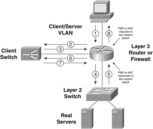 To get started with your inline mode configuration, there are two VLANs that you must include when designing your server farms:
Note You can also put clients and servers that you do not intend to load balance in your client VLAN. There they can access the virtual servers themselves, if necessary. As an example, a client directly behind the Layer 3 router in Figure 10-15 sends a TCP SYN request to the virtual server. When the router receives an Ethernet frame for the virtual server, it performs a routing table lookup and determines that the destination address of the packet is reachable via its directly connected interface. Next, the router determines the MAC address of the virtual IP address (VIP) by sending an ARP request on the client VLAN. The content switch responds with its Ethernet interface MAC address. In fact, all virtual servers that you configure on the content switch in the client VLAN 10 resolve to the MAC address of the content switch's client VLAN Ethernet interface. The Layer 3 router then forwards the packet to the content switch's MAC address at Layer 2. The content switch receives the TCP SYN and, in this example, performs delayed binding by responding to the client with a TCP SYN/ACK response. When the handshake completes, the content switch chooses the real server with IP address 10.1.10.100 for the request. The content switch performs the TCP three-way handshake and bridges the HTTP GET request to the real server. Figure 10-15 illustrates this flow. Figure 10-15. Tracing a Flow in Content Switching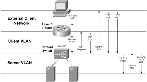 You can configure your content switches to behave as either routers or bridges. Bridge-Mode Content SwitchingTo configure your CSS in bridge mode, you simply configure your client and server VLANs with the same VLAN number. You must also configure the client and server subnets as the same. Figure 10-16 illustrates a CSS in bridge mode. Figure 10-16. A CSS in Bridge Mode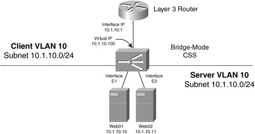 Note Because the CSS handles bridged packets in software, unless absolutely necessary, you should avoid configuring your CSS in bridge mode. Instead, you should configure your CSS in router mode, where packets are processed in hardware. Alternatively, the CSM handles both bridge- and router-mode traffic in hardware. To configure your CSS for bridge mode, you can use the configuration in Example 10-2.You must configure the default gateway of your servers as the IP address of the Layer 3 router (10.1.10.1). Example 10-2. Bridge-Mode CSS Configuration
Note In Example 10-2, the owner section specifies your virtual servers (with the content command). The owner concept comes from the managed hosting industry where an ASP manages the content switch on behalf of multiple clients. You can also configure the CSS using the XML interface, as Example 10-3 illustrates. You must use HTTP to publish the XML configuration to the CSM. Some network management stations offer you the ability to post XML to network devicesrefer to your specific network management station documentation for more details. Example 10-3. Bridge-Mode CSS XML Configuration
To configure your CSM in bridge mode, you configure the server VLAN in the same IP subnet as the client VLAN, but you configure them with different VLANs. That is, you separate them at Layer 2 with VLANs, but not at Layer 3 with IP subnets. The CSM bridges IP traffic between the two VLANs, creating a single Layer 3 subnet. Figure 10-17 illustrates a CSM in bridge mode. Notice that the highlighted IP addresses in the configuration are the sameidentical IP addresses on the server and client VLANS make the CSM work in bridge mode. Figure 10-17. CSM Bridge-Mode Configuration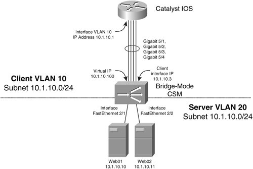 To configure your CSM for bridge mode, you can use the configuration in Example 10-4. Example 10-4. Bridge-Mode CSM Configuration
To configure your CSM for bridge mode using the CSM XML interface, you can use the configuration in Example 10-5. Refer to your CSM product documentation for the full CSM DTD that contains all the available XML tags for our CSM configuration. Notice that, unlike with the CSS, you cannot configure the MSFC interfaces and VLANs using XML. Example 10-5. Bridge-Mode CSM XML Configuration
Although you configure the CSM using the Catalyst 6500 or Cisco 7600 series command line and XML, Figure 10-17 illustrates that you should consider the CSM as a logically separate device that is one "router-hop" away from the Catalyst 6500 Layer 3 switch or Cisco 7600 series router. If you do not use your Layer 3 Multilayer Switch Feature Card (MSFC) in your switch to route packets to/from the CSM, then it's much easier to see that the CSM is one router hop away from your nexthop external router. Note The CSM is not supported in the Catalyst 6500/7600 without an MSFC present. You learned previously from Figure 10-11 that the CSM has four Gigabit Ethernet connections switch fabric. Because the CSM in Example 10-4 is installed in module 5, the interface between the CSM and the Catalyst switch is four Gigabit Ethernet interfaces with the names Gigabit 5/14. You can verify these interfaces using the show interfaces exec command. In Example 10-4, the interface vlan command configures the logical interface of the Catalyst 6500 MSFC facing the CSM. You assign an IP address to the interface of the CSM that is facing the Catalyst switch using the ip address command in VLAN client/server configuration mode on the CSM. The VIPs that you configure on the CSM with the virtual command will appear in the ARP tables of the MSFC that is connected to the CSM client VLAN interface. As such, the CSM responds to ARP requests from the MSFC for its VIPs, as you learned previously in Figure 10-15. The switchport access command assigns the server VLAN to the ports to which the real servers connect. To configure the CSM, you must enter the module ContentSwitchingModule command, or module csm for short, specifying the module number into which you installed the CSM. The configuration that tells the CSM to enter bridge mode is identical IP addresses assigned to both CSM client and server VLANS, as highlighted in Example 10-4. You should use the gateway command in client VLAN configuration mode to configure the CSM to route its traffic to the client VLAN interface you configure in the Catalyst MSFC. If you want to bypass your MSFC, configure the gateway to point to the next-hop router or firewall toward your clients. As you learned previously, to enable the CSM to inspect HTTP 1.1 requests for persistent GET requests, use the persistent rebalance command. CSM bridge-mode is useful when your non-load balanced servers are in the same subnet as your server farms. For example, in case you want to introduce the content switching to a subnet of servers without changing the IP address configuration on the servers, you can use bridge mode content switching. You simply need to add a new server VLAN, and allocate the existing VLAN as the client VLAN. This way, all devices in the client VLAN can directly access the virtual servers you configure in the client VLAN. Notice that Example 10-4 does not configure the client VLAN on any Catalyst ports, but in this case, you would leave your existing ports assigned with the client VLAN. If real servers within your server farms require originating connections to other virtual servers whose real servers are in the same VLAN/Layer 2 broadcast domain, you must make concessions to avoid the origin server using an optimal route to the requesting server. This concept is also known as triangulation, because the traffic flows in a triangular shape, with the requesting server, content switch, and origin server as the corners of the triangle. For example, in Figure 10-18, the real server Web02 from within the server farm WebFarm requires sending mail to the virtual server MailVIP. The content switch receives the TCP SYN request for its VIP, and selects real server Mail01 to send the TCP SYN request to. The content switch then performs destination NAT on the TCP SYN packet to the real IP address of Mail01. However, Mail01 will recognize that the Web02 is on the same subnet as itself, based on its routing table entry for 10.1.10.0/24, and will therefore send an ARP request directly for the MAC address of Web02. When the SYN/ACK packet from Mail01 reaches the Layer 2 switch, the Layer 2 switch forwards the SYN/ACK packet directly to Mail01. Because the Layer 2 switch has the switch port-to-MAC address mapping in its forwarding tables, the SYN/ACK never reaches the content switch. The content switch must receive the return SYN/ACK in order to perform DNAT, because Web01 is expecting the SYN/ ACK response from the content switches' VIP, not Mail02's real server IP address. When Web01 receives the SYN/ACK, it terminates its connection by not sending its TCP ACK to complete the connection. Figure 10-18. Server Farms Accessing Each Other in Bridge Mode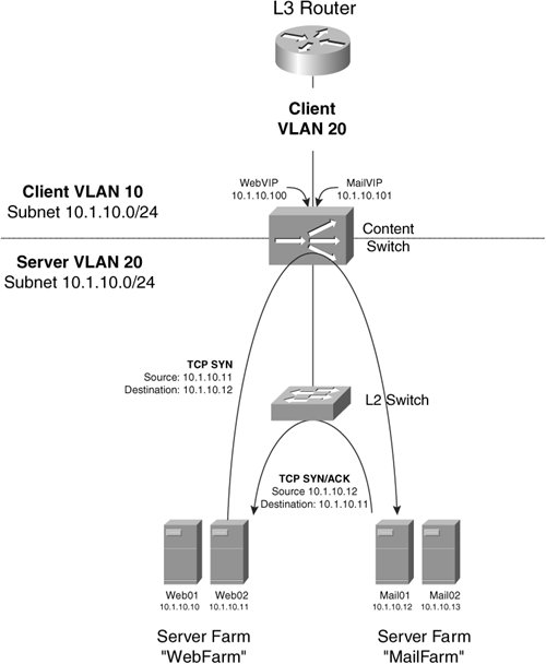 You can avoid bypassing your content switch at Layer 2 in four ways, and thus force return packets back through the content switch.
natpool pool-name beginning-address ending-address netmask mask You then assign this pool to the server farm with the nat client pool-name virtual server command. For example, the following command creates a pool to SNAT server-originated connections: natpool src-nat-pool 10.1.10.100 10.1.10.100 netmask 255.255.255.255 To configure your CSS to NAT real servers that originate connections, you can use a source group as follows: group web_group vip address 10.1.10.100 add service web01 add service web02 Source groups NAT the source IP address of the real server's outgoing packets to the VIP you configure for the group. If you want to instead NAT incoming requests to the mail farm, you can create a source group to NAT all incoming requests to the VIP of the source group. The following configuration triggers when clients (that is, one of the web servers) access the virtual server of the farm MailFarm. This also ensures that your mail servers respond through the CSS: group mail_group vip address 10.1.10.101 add destination service mail01 add destination service mail02 Be aware that all requests to the server farm will be source NATed with this configuration, precluding the use of source IP address auditing on your real servers.
Router Mode Content SwitchingIn secure router mode, you separate the client and server VLANs at both Layer 2 and Layer 3, and the content switch can then route between the two VLANs. Figure 10-19 illustrates a CSS in router mode. You should configure the default gateway of the servers as the content switch in router mode. Figure 10-19. A CSS in Router Mode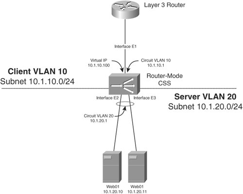 Example 10-6 gives the router-mode CSS configuration for the network in Figure 10-19. The circuit VLAN 20 interface is the default gateway of your real servers. The CSS routes between circuit VLAN 10 and VLAN 20. Example 10-6. Configuring Your CSS in Router Mode
To configure a CSM in router mode, you can use the configuration in Example 10-7, based on the design in Figure 10-20. The configuration that enables the CSM in router mode is the different IP address highlighted in Example 10-7. The server VLAN interface is the default gateway of your real servers. The CSM routes between server VLAN 10 and VLAN 20. Figure 10-20. A CSM in Router Mode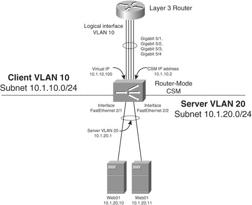 Example 10-7. Configuring Your CSM in Router Mode
By default, the CSM denies access to your real servers, which is why the common term for CSM router mode is "secure" router mode. To enable direct access to your real servers, you can add the configuration in Example 10-8 to your MSFC (or next-hop router) and CSM. The static route informs the MSFC router to route all packets destined to the subnet of the real servers (10.1.20.0/ 24) to the CSM IP address (10.1.10.2). You need to create a new server farm and specify the load-balancing algorithm with the command predictor forward. This tells the CSM to route packets according to the CSM routing table. In this case, the real subnet is directly connected to the CSM, so the CSM forwards packets directly to the real servers. Your new virtual server matches the subnet of the real servers for packets of any protocol, as specified with the any keyword. Example 10-8. Configuring Direct Access to Real Servers
|
EAN: 2147483647
Pages: 178