Exploring Your Server Load-Balancing Devices


Cisco developed the Local Director, its first standalone load-balancing appliance, in the mid-1990s. Toward the late1990s, Cisco embedded the IOS SLB feature within the Cisco IOS for basic SLB functionality. Cisco retired the Local Director in 2001 and concerted content switching development efforts on the more powerful CSS and CSM products. Although SLB has been available in Cisco IOS since the late 1990s, and you can still use it for very small data center environments, the CSS and CSM provide you with a superior hardware platform and robust SLB feature support.

Unique to the CSS and CSM is their customized hardware for connection processing, packet forwarding, and control processing.

  • Connection processing hardware Content switches use specific connection processing hardware for TCP/UDP connection maintenance, virtual server lookups, delayed binding, Layer 57 load-balancing decision making, in-band health checking, and the required packet transforms (that is, sequence number remapping or NAT translations or both). The connection processor processes persistent HTTP 1.1 requests, in order to perform HTTP request rebalancing.

  • Packet forwarding hardware The packet forwarding hardware is responsible for forwarding packets that are part of existing TCP/UDP connections, enabling packets to bypass the connection processor, thus effectively streamlining packet flow. The forwarding hardware can also perform packet transforms on packets of existing connections, if the connection processor instructs it to do so. The packet forwarding hardware is highly optimized, because it processes many more packets than the connection processing hardware.

    Note

    The connection processing and packet forwarding hardware are not necessarily separate hardware but are together logically called the datapath because they carry out operations on live data traffic. The connection processing hardware is sometimes called the session processing path, and the packet forwarding path is also called the fastpath. For complex operations, such as HTTP 1.1 persistent connections and Layer 57 load balancing, these two paths may work together.


  • Control processing hardware In addition to the connection and forwarding hardware, the CSS and CSM have special control processing hardware. The control processor handles all control traffic, such as ARP, HSRP, and ICMP, to the VIPs and operational management functions, such as the command line, web, XML, Dynamic Feedback Protocol (DFP), and SNMP interfaces. The control processor is also responsible for the systems management functions, including management of configuration files, system images, booting, and diagnostics. The control processor manages the status of real and virtual servers and actively takes servers on- and offline, when necessary. To do so, the control processor issues out-of-band health checks and inspects the responses from the real servers, resulting in a high level of administrative overhead. The control processor is a shared component of the CSM architecturethe other two hardware components access the control processor through a shared hardware bus, as you will learn later in this Chapter.

Note

The control processing hardware is also called the slowpath.


Content Services Switch

The CSS 11500 series is a standalone modular appliance, designed for any size of data center environment. The following module types make up the architecture of the CSS:

  • Switch Control Modules (SCM) The SCM is the central management module containing the control processor. The SCM comes with 2-Gigabit Ethernet ports supporting small-form factor pluggable gigabit interface converters (SFP GBICs), a console port, and Ethernet port for management. The SCM also has two PCMCIA slots that each support 256-MB flash memory disks or 512-MB hard disks.

  • Input/Output (I/O) modules I/O modules are available in the following port densities:

    - Two-port Gigabit Ethernet

    - Sixteen-port Fast Ethernet

    - Eight-port Fast Ethernet

  • Session Acceleration Modules (SAM) The SAM offers an increase in performance, without the cost of additional ports. The SAM provides the same flow setup mechanism as the other modules.

  • SSL processing modules The SSL module adds hardware-based encryption capabilities for e-commerce applications. The SSL module delivers 1000 SSL transactions per second and 250 Mbps of RC4 symmetric key bulk data encryption. The SSL module also offers accelerated Rivest, Shamir, and Adelman (RSA) public key encryption for establishing SSL sessions.

Each of the modules in the preceding list includes a network processor (NP), which is responsible for the forwarding processing. Additionally, the NP interfaces the module into the switch fabric. Each module also contains a classification engine (CE) for accelerating access control list (ACL) processing and address resolution protocol (ARP) table lookups.

The NP contains four 200-MHz CPUs, each with its own direct access to the CE, thereby substantially decreasing the load on NP resources so that it can concentrate more on packet forwarding. The forwarding processors within the NP use the DRAM memory for packet buffering. The session processor (SP) is responsible for the connection processing of the switch and control processing on the SCM.

The beauty of this architecture is that it is scalable, enabling an increase in overall performance with the addition of any type of module to the chassis. In other words, the NP, SP, and CE within any module can process their own packets, or the packets of any other module. The SAM module always processes packets of other modules, because it does not have any I/O interfaces of its own. Figure 10-5 illustrates the CSS switching architecture.

Figure 10-5. The CSS Switching Architecture


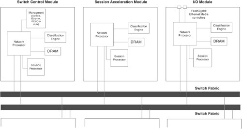
The CSS I/O modules distribute incoming flows evenly across the available modules. For example, if three clients initiate flows from the I/O module in Figure 10-5, the I/O module switches one request to the SCM and another to the SAM, and processes one itself.

CSS Packet Flow

Consider an example in which a client, located upstream via the Fast Ethernet I/O module B in Figure 10-6, issues a single HTTP request for the virtual server configured previously in Example 10-1. The real servers for this virtual server are reachable via Fast Ethernet ports on a different module within the CSS chassis (I/O module A). Figure 10-6 illustrates the flow of this packet through the CSS.

Figure 10-6. CSS Packet Flow


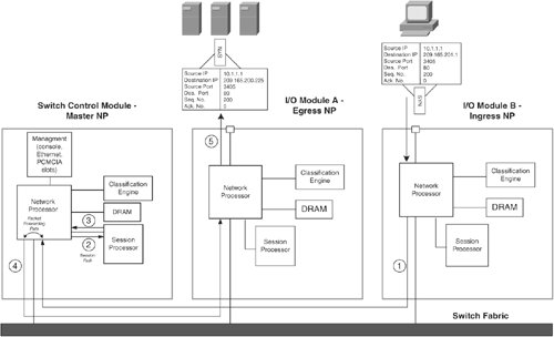
The packet takes the following steps through the CSS:

Step1.

The NP in I/O module B receives the TCP SYN segment from the upstream client and arbitrarily selects the SCM as the master NP to switch the request to.

Step2.

The master NP determines that the packet is for a new connection and performs an ARP and ACL lookup in the CE. The NP forwards the packet and the results of the ARP and ACL lookups to the master SP. The master SP then performs a virtual server lookup. The SP finds a matching virtual server, based on Layer 34 rules. The master SP then selects the real server to forward the request to, NATs the packet to the real server IP address, and recalculates the packet checksum.

Note

If the CSS in this example were to use a virtual server configured with Layer 57 policies, the master SP would perform delayed binding with the client before continuing to step 3.

Step3.

The master SP informs the master NP of the NAT requirements for subsequent packets of the flow, thereby enabling the rest of the flow to bypass the connection processing function of the SP. The NP also stores the return path at this step, enabling return packets to be NATed in the reverse direction.

Note

Steps 2 and 3 make up the session path that packets take for new connections. Packets of existing connections skip steps 2 and 3. Instead, they follow the packet forwarding path, as shown in Figure 10-6.

Step4.

The master SP then selects which egress NP it will forward the packet to, based on MAC and ARP address tables maintained within the CE.

Step5.

The Egress NP then forwards the packet to the downstream server and stores connection information for the packet, such that it selects the same master NP for the return packets.

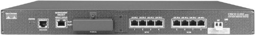
In the example in Figure 10-6, the single I/O distributes the total load between three modules. If you add another SAM to this CSS, the I/O module would further distribute the load across four modules.

CSS Models

The CSS chassis is available in three different form factors, each with the NP/SP/CE architecture described previously:

  • CSS 11501 As a fixed-configuration 1 rack-unit (RU) stackable switch, this switch includes an embedded SCM module and does not support the addition of other modules. It has a console port, an Ethernet management port, two PCMCIA slots for a combination of 256-MB flash or 512-MB hard disks, eight 10/100 ports, and one Small Form Factor Pluggable (SFP) GBIC Gigabit Ethernet port. The CSS 11501 does not support the modules, memory, and SFP GBICs as do the other modules. The CSS 11501 supports 6-Gbps aggregate throughput. Figure 10-7 shows the front of a CSS 11501 chassis.

    Figure 10-7. The CSS 11501 Content Switch

  • CSS 11501 with SSL termination The same specifications as the CSS 11501 but includes embedded SSL termination. The CSS 11501 with SSL supports 1000 SSL transactions per second and 250 Mbps of RC4 symmetric key bulk data encryption. The SSL module also supports data GZIP/deflate compression.

  • CSS 11503 Supports one SCM, and any two of the I/O, SAM or SSL modules. Only a single switch fabric and power supply is available in the CSS 11503. Each module has 1.6 Gbps connectivity to the switch fabric, resulting in 10 Gbps aggregate throughput. Figure 10-8 shows the front of a CSS 11503 chassis.

    Figure 10-8. The CSS 11503 Content Switch

  • CSS 11506 Supports two SCMs (with one in standby mode) and any five (four, if you are using a standby SCM) of the I/O, SAM, or SSL modules. Like the CSS 11503, each module has 1.6 Gbps connectivity but includes dual switch fabrics, resulting in 20 Gbps aggregate throughput. The CSS 11506 (see Figure 10-9) supports an additional power supply.

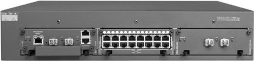
Figure 10-9. The CSS 11506 Content Switch


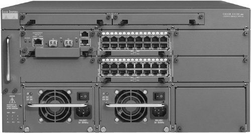
Table 10-1 gives the specifications for these content switches.
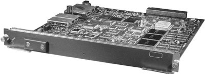
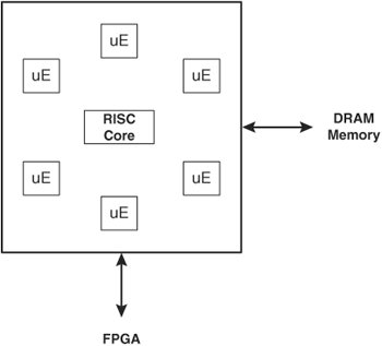
Table 10-1. Cisco CSS Series Content Switch Specifications
 

Cisco CSS 11501

Cisco CSS 11503

Cisco CSS 11506

# of Available Modules

0 (Fixed Configuration)

3

6

Default Hardware

Switch Control with 8 10/100 Ethernet and 1 Gigabit Ethernet (GBIC) Port

Switch Control Module with 2 Gigabit Ethernet (GBIC) Ports

Switch Control Module with 2 Gigabit Ethernet (GBIC) Ports

Maximum 2-port Gigabit Ethernet I/O Module

-

2

5

16-port 10/100 Ethernet I/O

-

2

5

8-port 10/100 Ethernet I/O

-

2

5

SSL Modules

-

2

4

Session Accelerator Modules

-

2

5

Maximum Gigabit Ethernet Ports

1

6 (includes 2 on the SCM)

12 (includes 2 on the SCM)

Maximum 10/100 Ethernet Ports

8

32

80

SSL Termination Available?

Yes, as a separate appliance

Yes

Yes

Redundancy Features

· Active-active Layer 5 Adaptive Session Redundancy (ASR)

· VIP redundancy

· Active-active Layer 5 Adaptive Session Redundancy

· VIP redundancy

· Active-active Layer 5 Adaptive Session Redundancy

· VIP redundancy

· Active-standby SCM

· Redundant switch fabric module

· Redundant power supplies

Height

1.75 in. (1 rack unit)

3.5 in. (2 rack units)

8.75 in. (5 rack units)

Bandwidth Aggregate

6 Gbps

20 Gbps

40 Gbps

Storage Options

512-MB hard disk or 256-MB flash memory disk

512-MB hard disk or 256-MB flash memory disk

512-MB hard disk or 256-MB flash memory disk

Power

Integrated AC

Integrated AC or DC

Up to 3 AC or 3 DC


Content Switching Module

The Content Switching Module (CSM) is an integrated services module that you can install in your Catalyst 6500 series switch or Cisco 7600 Series Internet routers. Figure 10-10 shows the CSM.

Figure 10-10. The Content Switching Module


The CSM supports four 1-Gigabit connections into the switching fabric, which the CSM multiplexes into the processing fabric. The CSM has a pipeline NP architecture in which packets traverse a series of stages that apply logic or modifications to the packet. Figure 10-11 illustrates the CSM pipelined architecture.

Figure 10-11. CSM Pipelined Architecture


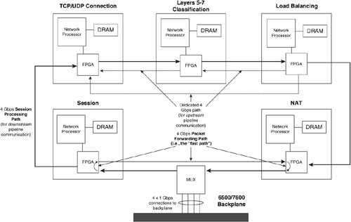
Note

Do not confuse HTTP "pipelining," which you learned about previously, with the CSM "pipeplined" architecturethey refer to different concepts.


Each stage contains a Field Programmable Gate Array (FPGA), 128 MB of DRAM memory, and an NP. Each NP has an Intel IXP 1200 processor containing six RISC microengines (uE) and a RISC core, as Figure 10-12 illustrates. The seven IXP subprocessors can operate in parallel on packets from different flows. A particular IXP provides 1 billion operations per second, giving the CSM an aggregate 5 billion operations per second across the five stages of the pipeline. The FPGAs are the physical connection points between each stage of the architecture, providing an addressable communications mechanism between the NPs. For example, if one stage needs to communicate with another in the pipeline, the intermediary FPGAs simply forward the packet to the next FPGA until the packet reaches the requested stage.

Figure 10-12. Network Processor Architecture


Note

You can view the use of the CSM IXPs using CiscoView Device Manager for the CSM. You can also see the statistics for individual IXPs using the command show module csm mod-num tech-support processor IXP-num command. You can also use the show module csm mod-num tech-support fpga command to display the FPGA statistics.


The NPs within each stage also maintain a connection to a shared PCI bus. The control processor provides a dedicated general-purpose PowerPC CPU for performing out-of-band health checking and configuration management to avoid increases in administrative processing from affecting the session or forwarding paths. Additionally, because the control processor is a general-purpose CPU, its functions are performed in software, as opposed to in hardware that uses IXPs, and the functions are therefore much more flexible (albeit slower) when performing the control functions. Figure 10-13 illustrates the control processor's placement in the CSM.

Figure 10-13. The Shared PCI Bus for Control Processing


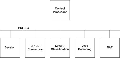
The CSM pipeline operates in a manner that is similar to an automobile assembly-line system. While some algorithms are being computed at one stage of a data pipeline, others are computed at a later stage of the same pipeline.

When a packet arrives at the CSM, the session stage is the first to process the packet, as you saw previously in Figure 10-11. The session stage determines whether the packet is part of an existing connection or a modification of an existing connection, such as an HTTP pipelined GET request. If it is part of an existing connection, the session stage sends the packet directly to the NAT stage through the packet forwarding path, completely bypassing the session forwarding path. Otherwise, the session stage forwards the packet through the session forwarding path to the TCP/UDP connection stage.

The TCP/UDP connection stage maintains the connection information for the flow, ranging from creating and removing entries from its connection state table, and performing delayed binding on flows matching Layer 57 policies, to performing virtual server lookups. For flows matching Layer 57 policies, the TCP stage passes the packet and its virtual server lookup results to the Layer 57 classification stage. The Layer 57 stage parses the content of the packet for cookies or URLs, using regular expressions that you configure on the CSM, and passes the packet and its results to the load-balancing stage.

For Layer 3 and 4 policies, the TCP/UDP stage bypasses the Layer 57 stage by addressing the FPGA of the load-balancing stage instead. That is, the load-balancing stage can receive packets from either the TCP connection or Layer 57 stages. The load-balancing stage applies the load-balancing algorithm, persistence policy, and fail-over mechanism associated with the virtual server you configured for the flow. For flows that require modification to the TCP connection entry during the load balancing or Layer 57 inspection process, both the load balancing or Layer 57 stages may communicate directly with the TCP stage over a secondary 4 Gbps communication path, as Figure 10-11 illustrates. The load-balancing stage then passes the packet and results to the NAT stage. The NAT stage is the final stage in the pipeline and is responsible for performing the packet transforms, such as NAT and sequence number remapping, and forwarding the packets to the MUX for transmission to the real servers or clients.


Content Networking Fundamentals
ISBN: 1587052407
EAN: 2147483647
Year: N/A
Pages: 178

flylib.com © 2008-2017.
If you may any questions please contact us: flylib@qtcs.net