Transport Layer
| Now that you have learned about the physical, data link, and network layers, you can tackle the intricacies of the transport layer. Whereas these lower layers deal with information within the network on a hop-by-hop basis, the transport layer works in an end-to-end fashion, between the communicating hosts. It provides the mechanism for ensuring that the content arrives in a fashion suitable to the particular application. The following are the transport layer protocols used in the TCP/IP protocol suite.
Transmission Control ProtocolApplications that require reliability must first open a TCP connection for communication between the client and server application to commence. The beauty of the OSI layered model is that an application may deliver content over an underlying TCP connection and trust that the data will arrive as it was sent without worrying about the underlying transport details. Note The concept of an application session is different from that of a TCP connection in that a session may maintain multiple TCP connections simultaneously or open individual short-lived TCP connections to transmit the application content. Each application may use the controls of TCP differently within a session to ensure optimal delivery of the given content. Application content is partitioned by TCP into smaller chunks of data that are transported in TCP segments. Figure 2-17 gives the TCP segment format. Figure 2-17. TCP Segment Format Table 2-6 outlines the TCP segment header fields in the TCP header.
TCP Three-Way HandshakeTo transport content reliably, TCP relies on sequence numbers to define the order in which segmented content must be assembled upon reception. Every data octet (or byte) in a TCP segment is logically assigned a sequence number. The sequence number in a TCP segment header references the first octet in the payload of the segment, residing directly after the TCP header, as illustrated previously in Figure 2-17. Consider the following example in which a client requires information from a server. The client application generates a content request to send to the server. TCP segments the content request into chunks of data that are appropriately sized for an IP packet. Before sending the content request to the server, a TCP connection is established, as illustrated in Figure 2-18. TCP segments are sent in the direction of the arrows, with time proceeding downward. Figure 2-18. The TCP Three-Way Handshake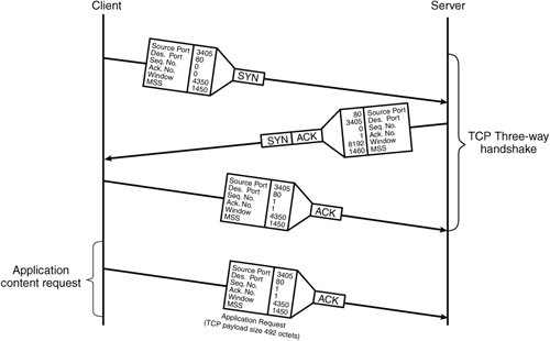 The TCP three-way handshake is used to synchronize TCP sequence numbers and exchange TCP options between TCP devices. In the example in Figure 2-18, the client generates a TCP SYN segment, with an initial sequence number, suggested receiver windows size, maximum segment size (MSS) TCP option, and the SYN flag set in the transport segment header. The segment is then sent to the server. The server acknowledges the client's receiver window size and initial sequence number by sending a TCP SYN-ACK segment back to the client. The SYN-ACK contains the server's initial sequence number, suggested receiver window size, MSS TCP option, and both the SYN and ACK flags set in the TCP segment header. At this point of the handshake, the connection is half-opened. Not until the client further acknowledges the server's suggested values, by way of a TCP ACK segment, is the TCP three-way handshake completed. The TCP ACK segment simply contains the same information as the SYN segment except with both the sequence and acknowledgement numbers increased by one octet. Both the client and server are now aware of each other's sequence numbers and are thus synchronized. Note The acknowledgment number is the next anticipated byte number by the receiver. The acknowledgment mechanism is cumulative, so that an acknowledgment of octet YY indicates that all octets up to but not including YY have been received. A TCP connection is fully established between the client and server, and the client may send the application request to the server. Actually, both ends may transmit and receive application requests or content or both through the open TCP connection, depending on how the application chooses to use it. Furthermore, with the window size agreed upon, the sender transmits enough segments to fill the allowable window, even if previously sent segments have not been acknowledged. This enables more efficient use of available bandwidth by using much less for the overhead that is associated with acknowledging every segment. Note In the example in Figure 2-18, the client connects to the well-known destination TCP port 80 for HTTP on the server. With HTTP, the client generates a random source port (3405) to distinguish between other TCP connections to the same server. With some applications, such as FTP, the source port is also a well-known TCP port (that is, port 21). Either the client or server may initiate a graceful close of the TCP connection. To do so, the initiator of the close sends a FIN segment to indicate that it has no more data to send. The station on the other side of the close then sends a FIN-ACK segment to the initiator to acknowledge the close request. When the FIN-ACK is received, the connection is considered half-closed. The initiator of the close waits for the other station to finish sending its data and close its half of the connection. In the meantime, the initiator will not send data but must continue to receive data from the other station. To abnormally abort a TCP connection, either side sends a TCP RST segment. After sending a RST, the TCP host need not await an ACK segment in response, nor continue to receive data from the other side. This reset method uses much less overhead to close a TCP connection. It is meant for use by one host that is signaling to another to close the connection during application layer errors or for use by a user who chooses to abandon the application session. For example, when a user closes a web browser, the browser sends a RST to the server to abruptly close the TCP connection. Table 2-8 outlines the different variables thus far required by the client and server to send data over the TCP connection that results from the three-way handshake in Figure 2-18. Example values from Figure 2-18 are given in Table 2-8 as reference for the illustrations in subsequent sections in this Chapter.
For illustration purposes, both the client and server from the example in Figure 2-18 chose initial sequence numbers equal to zero. Under normal circumstances, however, the sequence number is chosen as a random number between 0 and 232 1 and is incremented as content is sent throughout the TCP connection. In Table 2-7, the client's initial sequence number increased to 493 from an application layer request shown at the bottom of the timeline in Figure 2-18. TCP Sliding WindowTCP uses a sliding window approach to provide TCP congestion control. Windowing provides the ability to mitigate issues related to network congestion and faults, such as missing or out-of-sequence segments. Buffering segments in the window, before processing them at the application layer, enables the receiving host to reorder out-of-sequence segments and retransmit missing segments. The scenario continues from the three-way TCP handshake shown previously in Figure 2-18, as the application server is now able to send data to the client, using the values in Table 2-8. In this example, the window size was chosen to fit three packets of length 1450 bytes. The application has eight of these equal-length packets to send to the client (11,600 bytes in total). Figure 2-19 illustrates how the TCP sliding window works in this environment. Figure 2-19. TCP Sliding Window Approach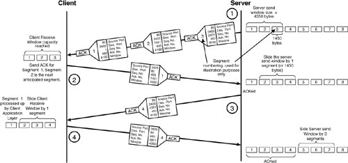 The following is the sequence of events that takes place during the first part of an application transaction, as illustrated in Figure 2-19.
The server then sends the next three segments consecutively but causes the receiver to become congested, as illustrated in Figure 2-20. A receiver may run low on buffer space that results from receiving packets faster then it is capable of processing. If this happens, the receiver advertises a smaller window size to the sender. The new window size regulates the transmission rate according to the receiver's processing capabilities. Figure 2-20. Window Resizing from Receiver Congestion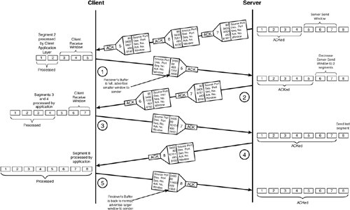 Figure 2-20 illustrates how the receiver must resize the window as a result of local congestion in its receive buffer. The following is the sequence of events that take place during the remainder of the transaction between client and server in Figure 2-20.
TCP Slow StartIn addition to detecting and recovering from local buffer congestion, as illustrated previously in Figure 2-20, the TCP sliding window mechanism is also used for detecting congestion within the network. Network congestion is caused from router packet queues overloading, which forces packets to be dropped or to remain in the queue for excessive periods of time before transmission. During periods of network congestion, the sender will detect the anomaly by segment timeouts or by receiving duplicate ACKs from the receiver. TCP uses timers to detect packet loss. When each segment is sent, the sender starts an individual timer for that segment. If the ACK is not received within the timeout value, the segment is resent. Alternatively, if a duplicate ACK for a segment is received by the sender, the segment is deemed missing and is resent. Figure 2-21 illustrates how congestion is detected by the server when a segment is lost in transmission and a duplicate ACK is sent by the receiver. Figure 2-21. Duplicate ACK Used to Detect Network Congestion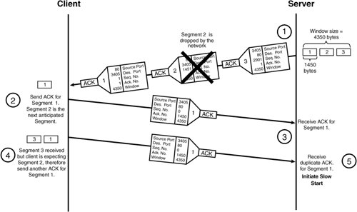 The following is the sequence of events that takes place when a packet is lost between client and server in Figure 2-21.
The server then initiates TCP slow start. With slow start, TCP assumes that the packet transmission rate is proportional to the rate of ACKs received by the sender. As individual ACKs are received, the sender's trust in the network increases. Specifically, when slow start is initiated, the sender creates a new variable called the congestion window (cwnd) and sets its value to 1. When the sender receives an ACK for the next TCP segment, it increases cwnd to 2 and sends two more segments. When the ACK arrives for the second segment in the window, the cwnd size is increased to 4, and four new segments are sent. When the ACK for the fourth segment arrives, cwnd is set to 8, and so on. The window increases in an exponential fashion until the precongestion window size is reached. TCP slow start is often used in conjunction with TCP congestion avoidance during periods of network congestion. TCP Congestion AvoidanceTraditionally, the TCP slow start exponential increase in cwnd would occur until the precongestion sender window size is reached. However, research has found that increasing cwnd in an exponential fashion until one half of the precongestion window size is reached proves to be much more practical in congested networks. Now when congestion occurs, cwnd is still set to 1, but a new variable, the slow start threshold (ssthresh), is set to half the precongestion window size. The ssthresh variable indicates when slow start ends and congestion avoidance begins. With congestion avoidance, TCP decreases the cwnd increase rate to a linear function from half to the full precongestion window size. As an example, Figure 2-22 illustrates the congestion avoidance mechanism using TCP slow start, with congestion occurring when the TCP window size reaches eight segments. Figure 2-22. Congestion Avoidance Using TCP Slow Start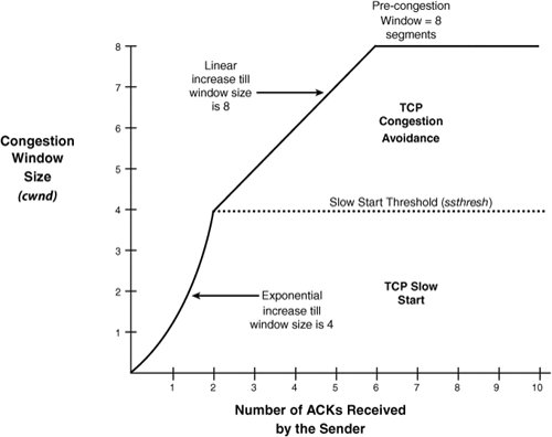 Note The TCP slow start and congestion avoidance causes problems if many users perform slow start at the same time. This global synchronization is resolved with Weighted Random Early Detection (WRED) discussed in Chapter 6. In typical TCP implementations, slow start is employed for every new connection that is established, not just when congestion occurs. In contrast, congestion avoidance is employed in conjunction with slow start only when congestion is detected by the sender. TCP Fast RetransmitRecall that, when a segment is transmitted, the sender starts a transmit timer for the segment. If an acknowledgement is not received within a timeout value, the segment is deemed lost and is retransmitted by the sender. However, as you saw previously in Figure 2-21, the missing segment is detected by the sender receiving duplicate ACKs, not by the send timer reaching the timeout value. In most cases, a duplicate ACK is received for a missing segment before the timeout value is reached. This normally reduces the time with which segments are detected as missing, which results in faster transmission of missing segments and an overall improvement in performance of TCP. The feature for detecting missing segments using the duplicate ACKs instead of the transmit timer is called TCP fast retransmit. Duplicate ACKs are also sent if out-of-sequence segments are received. To distinguish between out-of-sequence and missing segments, fast retransmit includes an increase in the number the ACKs (normally to three) that the sender must receive from the receiver before retransmitting the segment. Figure 2-23 illustrates how the TCP fast retransmit feature ensures that packets are actually missing, and not simply out-of-sequence. Figure 2-23. Duplicate ACKs from Out-of-Order Packets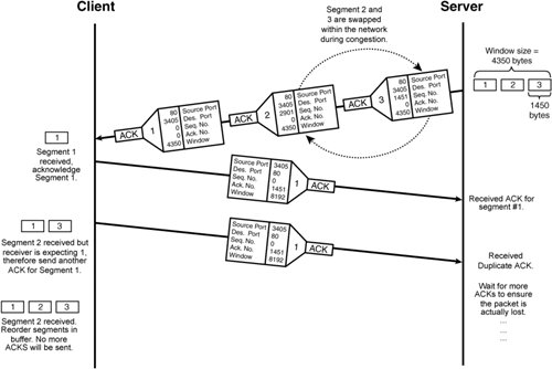 TCP Fast RecoveryAlthough duplicate ACKs detect network congestion, some segments are still being received by the receiver, which means that the network is only moderately congested. Recall that slow start reduces cwnd to one segment. This causes unnecessary bandwidth reduction during periods of only moderate congestion. Alternatively, when duplicate ACKs are detected by the sender, congestion avoidance is initiated instead. Congestion avoidance starts cwnd at half the precongestion window size, which results in a more conservative reduction in bandwidth during moderate congestion. This is called TCP fast recovery. TCP timeouts occur at the sender when no packets are being received by the receiver, which implies that the network is under severe congestion. Only when TCP timeouts occur is slow start initiated by TCP in conjunction with congestion avoidance. TCP Maximum Segment SizeFragmentation occurs when an IP packet is too large for the Layer 2 medium. IP packets cannot exceed the Maximum Transmission Unit (MTU), which ranges from 512 bytes to 65,535 bytes but is most often 1500 bytes for Ethernet networks. Recall that the maximum frame length for Ethernet II and IEEE 802.3 is 1518 to account for up to 1500 bytes of payload and 18 bytes of frame header. TCP has the ability to optionally negotiate a TCP option for setting the maximum TCP segment size, called the maximum segment size (MSS). MSS is used to ensure that the IP packet the segment resides in will not be fragmented. In the case of Gigabit Ethernet, jumbo frames can optionally be configured on the device to increase the MTU from 1500 bytes to 65,535 bytes, which drastically reduces Ethernet framing overhead. Bear in mind though that, if IP packets generated for jumbo frames are routed to slower speed links with lower MTUs, they will inevitably require fragmentation. Note Fragmentation is undesirable in content networking environments, because content switches direct packets based on Layers 57. Thus, if a packet spans multiple fragments, the content network device may have trouble enforcing its content policies. These issues are discussed in Chapter 10, "Exploring Server Load Balancing." TCP over SatelliteThe bandwidth for a single TCP connection is limited to the TCP window size divided by the end-to-end delay of the link. For example, for links with 750 ms delay, the bandwidth limitation imposed by a single TCP connection is approximately 85 kbps using the maximum TCP window size of 65,535 bytes. To overcome bandwidth limits caused by the maximum TCP window size, create an application session with multiple TCP connections and load share the content over the TCP connections. Load sharing over multiple TCP connections is often useful with high bandwidth satellite links, where the overhead associated with opening a connection is light enough to have a limited effect on the operation of the application. Alternatively, the bandwidth of a single TCP connection can be scaled by increasing the maximum window size. This is possible with the use of the TCP option called the window scale option (WSopt), as defined in RFC 1323. WSopt is used to scale the existing TCP window field in the TCP segment header of 16 bits by up to 2256 times. However, these window sizes consume much more buffer memory on the TCP hosts. TCP Variable SummaryTable 2-8 outlines the various TCP variables that are maintained on TCP hosts to communicate with one another, as discussed in this Chapter.
Note Content edge devices may tune the TCP parameters as discussed in Chapter 13, "Delivering Cached and Streaming Media." User Datagram ProtocolUser Datagram Protocol (UDP) provides segment delivery for applications that require efficient transport and tolerate loss of content. Unlike TCP, UDP does not:
The application using UDP is required to take responsibility for ensuring that the content is received intact. However, UDP ensures that segments arrive as they were sent by detecting errors in the UDP segment header and payload and will drop the packet if errors are found. Additionally, UDP provides simple Internet Control Message Protocol (ICMP) error reporting if the destination port is not available at the server. Note The ICMP error messages are also available for other IP-based transport protocols, not only for UDP. Figure 2-24 contains the UDP segment header fields. Figure 2-24. UDP Segment Header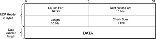 |
EAN: 2147483647
Pages: 178
- Chapter II Information Search on the Internet: A Causal Model
- Chapter V Consumer Complaint Behavior in the Online Environment
- Chapter X Converting Browsers to Buyers: Key Considerations in Designing Business-to-Consumer Web Sites
- Chapter XII Web Design and E-Commerce
- Chapter XIV Product Catalog and Shopping Cart Effective Design