| You are now equipped to learn how content is prepared for sending over a TCP/IP network. As an example, say you enter http://www.cisco.com into a web browser URL field and press Enter. Your client and the Cisco.com origin server perform the following steps before the web page is sent to your browser. Step1. | The hostname is resolved to an IP address using the Domain Name Service (DNS).
Note For more information on the operation of DNS, see Chapter 12. |
Step1. | A TCP connection is opened from the client to the cisco.com origin server IP address using the TCP three-way handshake as illustrated previously in Figure 2-18.
| Step2. | An HTTP GET request is written to TCP connection by the HTTP client application for the main page of the website. Figure 2-18 shows this GET request at the bottom of the timeline. This request is encapsulated and sent without any application data. The HTTP GET request resides in the header of the HTTP packet. Therefore, no application payload is necessary.
Note The HTTP protocol is discussed in detail in Chapter 8, "Exploring the Application Layer." | Step3. | The response from the server is encapsulated as illustrated in Figure 2-25.
|
Figure 2-25. A Detailed Network Trace 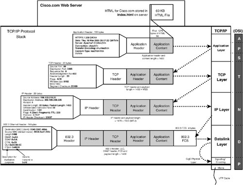
In this example, the main page for Cisco.com is between 200 KB and 250 KB with approximately 30 files, including HTML, images, and dynamic content embedded within the page. The HTML for the main page is approximately 60 KB of text, which takes approximately 40 packets at 1500 bytes each. For simplicity, Figure 2-25 illustrates encapsulating the first packet of the HTML text sent to the browser from the web server hosting Cisco.com. Most web browsers load the HTML page first, and then, as the HTML hyperlinks to graphics and dynamic content are received within the HTML page, additional GET requests are sent and the process in Figure 2-25 is repeated. The following is the series of encapsulations that the content in Figure 2-25 goes through before being transmitted by the Ethernet physical layer. Step1. | An HTTP header is added to the data chunk, with details such as the website URL, the HTTP method, and return code (the return code is "200 OK," in this case).
Note Notice that the HTTP header is much larger than the TCP and IP headers. This is because the field names are included in the HTTP request, whereas, in TCP and IP, they are implied. | Step2. | An HTTP application segment is then encapsulated by adding a TCP header. The destination port used is the port generated by the client in the original TCP handshake. The ACK flag is set, and the acknowledgement number for the client's previous request is used.
| | | Step3. | An IP header is then added to the TCP segment. The IP header includes Layer 3 information, such as source and destination IP address.
| Step4. | An IEEE 802.3 frame header and footer is then added to the IP packet. The header includes the source and destination MAC addresses. When this packet is transmitted by the Cisco.com server, the source MAC is the server MAC, and the destination is the default gateway of the origin server.
| Step5. | The Cisco.com origin server site is 1000BASE-T at the physical layer, in this example. The Ethernet frame is therefore transmitted over the UTP cable using PAM-5 to its default gateway router, ultimately destined to your web browser client.
|
|