Internet Protocol
| IP corresponds to Layer 3 of the OSI reference model. IP is a mechanism to deliver application content over a network in the form of small packets of information. IP will not guarantee that packets will arrive at the final destination as they were sentthey are transported with best-effort service only. IP checks for errors in the packet header but not for errors within the packet content. Furthermore, the TCP transport layer is responsible for retransmitting and reordering packets lost in transit or received out-of-order, respectively. Additionally, responsibility for packet content error checking is left to TCP. If an error is found in the packet header, IP simply drops the entire packet and assumes that the upper layers will detect a lost packet and, if necessary, retransmit it. TCP was developed as the reliable transport layer mechanism used in the TCP/IP protocol suite. TCP determines if there are missing, out-of-order, or erroneous packets, as mentioned previously. User Datagram Protocol (UDP) uses IP's best-effort service, but checks for errors within the packet content, as opposed to performing header error checking only, as performed by IP. However, unlike TCP, UDP discards the packet if errors are found. Like IP, UDP assumes that the application layer will detect missing or out-of-sequence content and, if necessary, retransmit it. Figure 2-14 outlines the IP packet format. Figure 2-14. IP Packet Format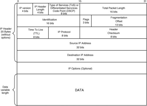 The various fields of the IP frame header are described in Table 2-6.
The 8-bit type of service (ToS) field includes IP precedence (3 bits), type of service (4 bits), and 2 unused bits. This field is used also for the Differentiated Services Code Point (DSCP) field definition. This newer definition uses 6 bits for conveying DSCP, giving a total of 64 possible classes. The currently unused (CU) 2-bit field is now mapped to the Explicit Congestion Notification (ECN) field. If a router is congested, the ECN field is set by the router using Weighted Random Early Detection (WRED) to notify downstream network devices of the congestion. Note For more information on ECN and WRED, see the section "Configuring Weighted Random Early Detection" in Chapter 6, "Ensuring Content Delivery with Quality of Service." Quality of service (QoS) in Cisco IOS uses either the IP precedence or DSCP for prioritizing traffic for delay-sensitive applications, such as voice and video. Figure 2-15 illustrates both the old ToS and new DSCP interpretations of this 8-bit field. Figure 2-15. The IP ToS and DSCP Service Field.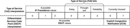 Content awareness at Layer 2 and Layer 3 is minimal, since little information about the content of the packet is available in the IP and Ethernet headers. However, content networking devices perform operations at this layer, based on content awareness at higher levels. For example, IP Multicast occurs at Layer 2 and Layer 3. Also, Network Address Translation (NAT) and application redirection is performed at Layer 3. Although IP is used to transport the following protocols, they are most appropriately located at the same OSI layer as IP (Layer 3):
Address Resolution ProtocolA host uses Address Resolution Protocol (ARP) when it wants to communicate with another host or router in its broadcast domain and knows the IP address but does not know the MAC address of the host or router. To determine the MAC address, the sender creates an ARP packet and encapsulates it directly in to an Ethernet frame. The sender inserts a broadcast destination MAC address and its own MAC as the source into the Ethernet frame header. The ARP request is broadcast to all devices in the broadcast domain, and the station that bears the requested IP address will send the ARP response directly back to the sending device. A broadcast domain is limited to a group of network devices that receive explicit broadcast requests originating from one another. This is normally limited to the IP subnet or Virtual LAN (VLAN) that the devices are located within, but will span multiple subnets if transparent bridging is used. You will learn topics on VLANs and bridging in Chapter 3, "Introducing Switching, Routing, and Address Translation." Figure 2-16 illustrates the process ARP uses to determine the MAC address for a given IP address. Figure 2-16. The MAC Address Resolution Procedure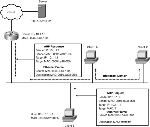 In Figure 2-16, Client B with IP address 10.1.1.3 generates an ARP request for its default gateway router address 10.1.1.1. The ARP request packet is then encapsulated in an Ethernet frame. Note For more information on data encapsulation, see the section "Putting It All Together with a Detailed Network Trace," in this Chapter. The Ethernet frame is broadcast on to the local segment, and the router responds with an ARP response containing its MAC address that is associated with the requested IP in the ARP request. Clients A and C ignore the ARP request because they are not assigned the request IP address. Now that Client B in Figure 2-16 knows the router's MAC address, it will route all traffic destined to the Internet server 209.165.200.226 directly through the router. Internet Control Message ProtocolICMP provides management and error reporting between TCP/IP devices. ICMP has many facilities to aid network devices in packet delivery. A few of its mechanisms that pertain to content networking are
Layer 3 Connectivity DeterminationICMP provides a simple request-response facility to determine the status of a TCP/IP device and the roundtrip times between two hosts. ICMP Echo requests are sent to a destination device that will in turn send an ICMP Echo response back, if an ICMP process is available on the device to yield a response. Because ICMP is often implemented entirely within the operating system or TCP/IP driver of the end device, responses to ICMP Echo requests almost always determine that the host is at least powered on and available on the network. As a result, even if applications that a server is meant to serve are not available, the server may respond to ICMP echo requests. A drawback to ICMP is that it runs at the IP layer and is therefore unreliable. This means that ICMP Echo requests or responses may get dropped along the path and cause additional problems during troubleshooting. The Ping utility automates ICMP echo requests and responses. Ping is therefore normally the first test to perform in determining whether a remote host is available or not. Note Because most Internet hosts and servers support ICMP, it is useful for calculating round trip times (RTT) between two devices. ICMP RTT is discussed in Chapter 12,"Exploring Global Server Load Balancing," for proximity determination in GSLB. The IP header contains a Time To Live (TTL) field that is set by the sender to the maximum number of routers (or hops) that a packet will encounter on the way to its final destination. An intermediary router will send an ICMP "TTL exceeded" error message to the sender that indicates that the TTL has been reached and will drop the offending packet. TTL field is also useful to avoid infinite loops. Unavailable Port ErrorsICMP sends error reports to clients in response to TCP or UCP requests for application layer services that are either not installed or currently unavailable. Because the application is unable to notify clients of the error at Layers 57, ICMP notifies clients on behalf of the application at Layer 3. Announcement of New Default RoutersHosts on an Ethernet LAN normally have only optimal TCP/IP configuration, including an IP address, a subnet mask, and a default gateway. When a LAN has multiple routers, a host's default router has the ability to direct hosts to another available router, if that router provides the more direct route to the ultimate destination. The default router updates the hosts routing table using ICMP redirect messages. The ICMP redirect message includes the IP address of the requested destination and the IP address of the next hop router that can route to the requested destination. The requesting host creates a host route in its routing table by using the information in the ICMP redirect message. A host route is a route to an individual destination host that is masked with a full 32 bit subnet mask to match the entire host portion of an IP address. For example, say another router is placed in the broadcast domain in the Figure 2-16 and functions as a default router for Client A in order to route to other subnets in the private network. The new router is not directly connected to the Internet and therefore requires the routing of all traffic destined to the Internet through the original router in the broadcast domain. As a result, the new router sends an ICMP redirect message to Client A, instead of routing the traffic to the original router on behalf of Client A That is, a host route to destination server 209.165.200.226 via the original router (with an interface IP of 10.1.1.1) will be installed in the local routing table of Client A, which will enable Client A to route to the Internet host 209.165.200.226 directly. Internet Group Management Protocol and Protocol Independent MulticastInternet Group Management Protocol (IGMP) is used by clients to inform neighboring multicast routers of the multicast groups that the client is part of. These IGMP messages are used by multicast routers to track host memberships on each of its directly connected networks. By requesting to be a part of a multicast group, a host will receive all traffic destined to the group. A router on an Ethernet segment will forward traffic from the requested group directly to the client. Protocol Independent Multicast (PIM) is a network layer multicast routing protocol used by Cisco routers. To route multicast traffic through the network, PIM uses your existing unicast routing protocol tables to determine the reverse path of the traffic (that is, the interface closest to the multicast source). Using Reverse Path Forwarding (RPF), PIM forwards the multicast traffic out all interfaces besides the reverse path interface. IGMP and PIM are described in detail in Chapter 5. |
EAN: 2147483647
Pages: 178