Ethernet Physical and Data Link Layers
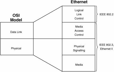
| Most professional positions in the Internetworking industry require that individuals have a working knowledge of the physical layer. Often, network cable installation and maintenance is the responsibility of the network administrator or manager, in addition to specific responsibilities associated with the particular role. This is also the case with most content networking roles, because installing and maintaining content networking products also requires physical layer cable and network interface management. Ethernet is the predominant protocol used in the content networking solutions. Figure 2-1 shows how the Ethernet layers coincide with the data link and physical layers of the OSI model. Figure 2-1. The Ethernet Protocols in Relation to the OSI Reference Model Physical LayerThe first layer of the TCP/IP protocol suite includes the mechanical and electrical properties for sending and receiving information between Ethernet network devices. Ethernet Mechanical PropertiesThe MediaThe mechanical properties for Ethernet depend on the type of physical medium, with copper, fiber, and wireless media available. Although wireless is increasing in popularity for desktop connectivity, copper and fiber are the most popular physical layer media used for content network deployments. Ethernet over CopperFor Ethernet over copper, unshielded twisted pair (UTP) network cables are most common. UTP includes four twisted pairs of small copper wire, with an 8-pin RJ-45 connector at both ends to connect to network interfaces. For the 10 Mbps over UTP (10BASE-T) and 100 Mbps over UTP (100BASE-T) standards, only two pairs of the four are used, with one pair for transmitting and the other for receiving data. Alternatively, all four wire pairs are used for 1000 Mbps (1000BASE-T), with each pair capable of both sending and receiving data. Note For Ethernet over copper, one wire of each pair is for transmitting a positive direct current (DC) voltage, and the other is for a negative DC voltage. UTP cable pinouts refer to the position that the eight individual copper cables are inserted into the pins of an RJ-45 connector. The pinouts are the same for all Ethernet-over-copper protocols, and are given in Table 2-2.
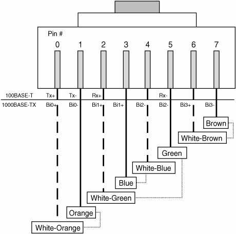
Figure 2-2 illustrates the groupings of the pairs within an RJ-45 connector. Although wires of the same color pairs (for example, [White with Color-X stripe, Color-X]) are twisted with each other within the cable itself, the two wires within the pair [White with Green stripe, Green] are separated and connected to pins two and five, respectively. The location of the receive (Rx), transmit (Tx), and bidirectional (Bi) signals are also given in Figure 2-2 for 10/100BASE-T and 1000BASE-T implementations. Figure 2-2. RJ-45 Connector Pinouts for Ethernet over Copper Using Standard UTP Cabling Ethernet over FiberFiber-optic technologies allow rays of light to travel over hair-thin strands of glass. Light rays are guided down the core of the glass fiber. The core is surrounded by additional fiber called the cladding that traps the light within core. The technique for containing light waves completely within the fiber core is called "total internal reflection." That is, if light rays are emitted at particular angles in relation to the center of the core, they will not refract in to the cladding, but will rather reflect back in to the core fiber. Figure 2-3 shows the various components of a fiber-optic cable, and how total internal reflection compares to light refraction in to the fiber cladding. Figure 2-3. Fiber Cross-Section Showing Fiber Core, Cladding, Total Internal Reflection, and Light Dispersion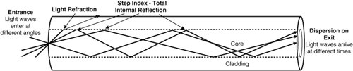 Ethernet over fiber commonly uses multimode (MM) and single mode (SM) fiber. MM fiber is designed to allow multiple light rays (called modes) through the core simultaneously. MM comes in two forms: step index and graded index. Step index fiber has the same fiber properties throughout core, resulting in a sudden refractive "step" into the cladding, as suggested previously by Figure 2-3. Rays entering at sharper angles will travel a further distance and, therefore, will arrive at the receiving end at a later point time than rays entering at duller angles. This difference in ray arrival times is known as dispersion. Step index is an older and slower technology than graded index, with the light source operating up to only 200 MHz, and is rarely used today because of dispersion. With graded index, variations are imposed in the composition of the glass in the core, resulting in a gradual increase in refractive index toward the core. The refractive index is the degree to which the fiber will bend the light rays. This results in a gradual narrowing of rays toward the center of the fiber. Figure 2-4 shows how the rays are guided through the core of the graded index fiber. Figure 2-4. Graded Index MM Fiber Cross-Section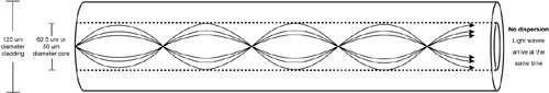 An important property of graded MM fiber optics is that rays travel more slowly and degrade faster toward the center of the core where the refractive index is highest. In Figure 2-4, although the outer light rays travel a longer distance than the inner rays, they are further away from the center and therefore travel faster than the inner rays. The result is that all light rays will arrive at the other end of the fiber at approximately the same time, thus overcoming the dispersion that occurs in step index fiber. Also notice that the rays no longer travel in straight lines but follow a more snake-like path that results from gradually being bent back toward the core. The bandwidth of graded index fiber is much higher than that of step index fiber, with source lasers capable of generating signals up to frequencies of 2 gigahertz (GHz). Two sizes of MM fiber are available: 62.5 micrometer and 50 micrometer-diameter core fibers, both with 125 micrometers of cladding. However, with SM fiber the core is reduced to 9 micrometers in diameter as illustrated in Figure 2-5, which allows only a single ray of light through the core. Indeed, with such a small diameter, only a single ray is necessary to sufficiently light-up the core in order to send a signal. In comparison, MM fiber requires numerous rays to light up the core. Furthermore, the single ray follows a direct route through the fiber; therefore, SM supports much higher frequencies (100,000 GHz+), over greater distances than MM fiber. Figure 2-5. SM Fiber Cross-Section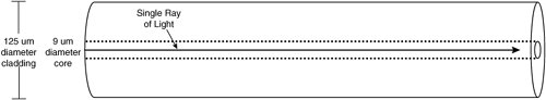 In comparison, if a single ray of light is sent straight down the center of a graded index MM fiber, it dissipates very quickly, because light degrades faster in the center of the MM core. In contrast, SM is able to sustain a single ray in the core because of the reduced core diameter, and the uniform fiber refractive index within the core. Additionally, dispersion is no longer an issue with SM fiber, because only a single light ray is used. The speeds of SM fiber can exceed terabits per second (Tbps), and SM fiber supports multiple channels of bandwidth over the same fiber using dense wavelength division multiplexing (DWDM). With DWDM, multiple wavelengths of light traverse the same fiber without interfering with one another, thus providing one channel of bandwidth per wavelength. Note Comparing multiple light rays in MM fiber to multiple wavelengths in DWDM (over SM fiber), the different rays enter into MM fiber using the same wavelength, but at different angles with respect to the cladding of the fiber. However, with multiple wavelengths in DWDM, each wavelength is independent of other wavelengths, which allows multiple channels of bandwidth to travel straight down the center of the SM fiber core without interfering with one another. MM fiber is used for shorter distances and lower bandwidths than SM fiber and is often used for server and desktop connectivity at 10, 100, and 1000 Mbps. MM fiber supports distances of 550 meters. SM fiber is typically used for connectivity at higher speeds and larger distances, upwards to 70 kms, between buildings or cities. Because MM fiber has a much wider core, the area through which to emit light is much smaller, and therefore less expensive lasers are required to generate the light ray. The drawback is that numerous rays of light are required to light up the MM core in order to propagate the same signal that requires only a single ray in SM fiber. Other important facts about fiber optics are
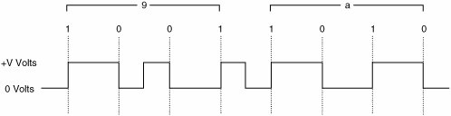
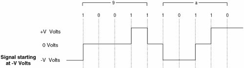
Ethernet Electrical PropertiesThe SignalingThe physical layer contains the electrical specifications and protocols that are responsible for encoding and transmitting data bits over physical wires. For Ethernet over copper, the bits are encoded and transmitted in terms of changes in direct current (DC) voltages. For Ethernet over fiber, changes in light intensity are used to convey binary data. Most 10BASE-T implementations use Manchester encoding for signaling bit streams. This method uses transitions in the signal for encoding individual bits. Logic one is represented as an upward transition in voltage and logic zero as a downward transition. Figure 2-6 illustrates how the hexadecimal byte 0x9a (or binary byte 0b10011010) is sent using Manchester encoding. Figure 2-6. Sample of the Manchester Encoding Scheme Used in 10 Mbps Ethernet Data Encoding A benefit of Manchester encoding is that the speed of the clock is the same as the bandwidth transmission rate (that is, 10 Mbps is transferred using a 10 MHz clock). A drawback to Manchester encoding is that only a single bit is conveyed within a full signal wave. To encode 100BASE-T, 4B/5B codes are used with Multi-Level Transition Level 3 (MLT-3) signaling. With MLT-3, three levels of voltage are used instead of two, as used in Manchester encoding. That is, MLT-3 cycles between V to 0 to +V then back to V, repeating indefinitely. Logic zero is encoded by stopping the cycle for one transition. Logic one is encoded by continuing the cycle. Before the byte is transferred with MLT-3, it is first encoded using 4B/5B encoding. With 4B/5B encoding, each hexadecimal 4-bit digit is encoded into an essentially uncorrelated 5-bit code, using the 4B/5B translation table in Table 2-3.
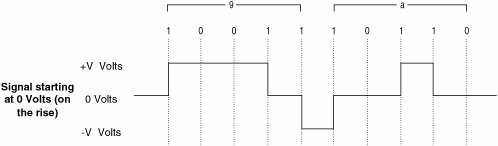
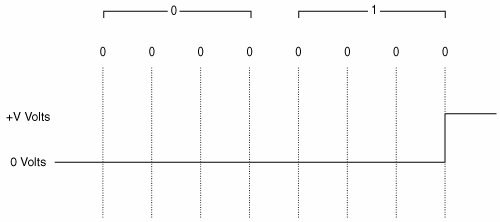
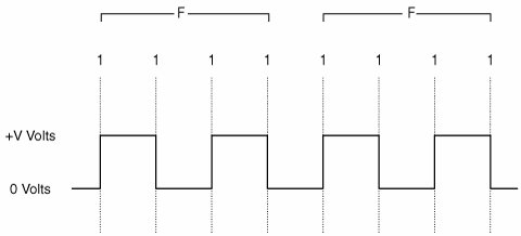
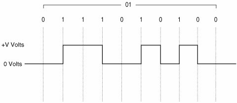
The hexadecimal byte 0x9a is transferred using the codes 0b10011 and 0b10110 according to the transitions in Figure 2-7 and Figure 2-8. Figure 2-7 shows the first example with the voltage starting at 0 volts on the rise to +V volts. Figure 2-8 shows the second example with the voltage starting at V volts. Although more bits are now being transferred (5/4ths more), the frequency of the clock is increased by the same proportion. For example, a 125 MHz clock transmits 100 Mbps of bandwidth. A benefit of 4B/5B with MLT-3 is that a full wave transmits two bits of data. Figure 2-7. 4B/5B with the MLT-3 Encoding Scheme (Voltage Wave Starting at 0 V) Figure 2-8. 4B/5B with the MLT-3 Encoding Scheme (Voltage Wave Starting at -V) With Non-Return to Zero (NRZ) signaling, binary zero is represented as zero voltage and binary one as +V voltage. NRZ is the simplest form of bit encoding but causes problems with clock synchronization when long strings of zeros or ones are transmitted. With an uneven balance of zeros and ones, the signal generated by the source clock may become unsynchronized with the receiving clock, causing the receiver to improperly decode the bit stream. As with 4B/5B and MLT-4, for every full wave, two bits of data are sent. Figure 2-9 shows how the hexadecimal byte 0x01 is encoded with NRZ. Figure 2-9. NRZ Signaling with a Long String of Zeros Leading to Potential Clock Synchronization With NRZ-Inverted (NRZ-I), the binary zero is represented by no change in voltage, and binary one is represented by inverting the voltage from the previous level. NRZ-I is slightly beneficial over NRZ in cases where there are more ones than zeros in the bit stream, because more transitions are made than NRZ for long strings of ones. However, long strings of zeros still cause clock synchronization issues with NRZ-I. Figure 2-10 illustrates NRZ-I to transmit the hexadecimal byte 0xff (or 0b11111111). Figure 2-10. NRZ-I Encoding Resolves Clock Synchronization Issues for Long Strings of Ones NRZ or NRZ-I must be used for Ethernet over fiber, because negative values are not supported in fiber transmission. That is, only two values are used for conveying the zeros and ones over fiber, by changing the light intensity within the fiber. For 100 Mbps over fiber (100BASE-FX), 4B/5B coding is used with NRZ-I signaling. For Gigabit Ethernet over fiber (1000BASE-SX/LX/ZX), 8B/10B coding is used with NRZ signaling. With 8B/10B, the code words are 10 bits long to convey 8 bits of data. Because the table now requires one code entry for each of the eight bit words, 28 (256) entries are required and therefore are not given here. The code words are formulated so that the number of zeros and ones are balanced, thus circumventing clock synchronization issues associated with NRZ. For the hexadecimal byte 0x01, the 10-bit code is 0b0111010100 and will therefore require more transitions in the signal using 8B/10B, as illustrated in Figure 2-11, than with NRZ-I alone, as illustrated previously in Figure 2-10. Figure 2-11. NRZ with 8B/10B Encoding with Fewer Zeros, Thus Reducing the Risk of Clock Synchronization Clock synchronization is important for Gigabit Ethernet because the clock speeds are 10 times faster than that of Faster Ethernet and 100 times faster than 10 Mbps Ethernet. Pulse Amplitude Modulation Level 5 (PAM5) signaling and coding is used for Gigabit Ethernet over copper (1000BASE-T) implementations. With PAM5, five voltage values (that is, 2, 1, 0, +1, and +2) are used to express the binary data. Using echo cancellation, PAM5 enables simultaneous transmission and reception on each wire pair. Consequently, each of the four pairs attains 250 Mbps throughput, thus achieving 1 Gbps aggregate throughput over the four pairs. In comparison to the other physical layer schemes in this Chapter, the signaling and coding structure of PAM5 is very complex. Therefore, its details are left for further reading. Organizations upgrading existing 100BASE-T networks to 1000BASE-T need not replace network UTP cables. Upgrading existing Network Interface Cards (NICs), leaving installed cabling in place, is sufficient to upgrade to 1000BASE-T. Table 2-4 shows the physical layer specifications for prominent Ethernet standards.
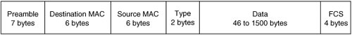
Data Link LayerWhereas the physical layer is responsible for transferring raw bits into streams of data, the Ethernet data link layer is responsible for determining what the streams mean and when the streams should be sent. For a receiver on a segment, Ethernet frames are created from the raw binary data provided by the physical layer. Because the physical layer merely accepts and transmits streams of zeros and ones without any sense of the structure of the data, it is up to the data link layer to create and recognize frames. Figure 2-12 and Figure 2-13 include the fields of Ethernet II and IEEE 802.3 frames, respectively. Figure 2-12. Ethernet II Frame format Figure 2-13. Ethernet 802.3 Frame format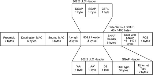 An Ethernet frame contains 14 bytes of header, 4 bytes of trailer, and between 46 and 1500 bytes of data. The various fields of the Ethernet frame formats from Figure 2-12 and Figure 2-13 are located in Table 2-5.
Note Any frame that is less than 64 bytes is called a runt, and one that exceeds 1518 bytes is known as a giant. Some Cisco Catalyst series switches support the forwarding of frames exceeding the maximum frame size of 1518, because some vendor NICs generate large frames to increase overall application bandwidth. See your Catalyst switch configuration manual for support details. Hosts on an Ethernet segment are configured to transmit in either full- or half-duplex mode. Hosts communicating with one another using half-duplex cannot transmit and receive data simultaneously. In half-duplex Ethernet environments, the LAN segment is shared among multiple hosts, resulting in the formation of a collision domain. When configured as half-duplex, network interfaces of Fast Ethernet speeds or higher support only two hosts on a segment, resulting in a collision domain containing two hosts. To send an Ethernet frame, and avoid a collision on the segment, the host must first determine if the carrier is in use by the other host. Ethernet provides contention resolution using Carrier Sensing Multiple Access/Collision Detection (CSMA/CD). This provides each station on the physical wire with a method to determine if the wire is in use and the ability to retransmit in the event of collision. If the wire is found to be in use, the station uses binary exponential back-off to retransmit the Ethernet frame. With this method, the station retransmits at a random time in the future, normally within a fraction of a second. If at that time the carrier is still in use, it doubles the previous time value and then attempts to retransmit. The method continues in this fashion until the carrier is free within the collision domain. Hosts communicating with one another using full duplex may transmit and receive simultaneously. Therefore, in full-duplex environments, the collision domain is non-existent and thus CSMA/CD is not used. That is, a device at the end of a full-duplex Ethernet link does not have to listen for other transmissions before sending data. |
EAN: 2147483647
Pages: 178
- Integration Strategies and Tactics for Information Technology Governance
- Linking the IT Balanced Scorecard to the Business Objectives at a Major Canadian Financial Group
- A View on Knowledge Management: Utilizing a Balanced Scorecard Methodology for Analyzing Knowledge Metrics
- Governance in IT Outsourcing Partnerships
- The Evolution of IT Governance at NB Power