Site-to-Site Deployment Examples
This section highlights configuration examples using Cisco routers as IPsec gateways. Each of the examples highlights a different method of building a site-to-site VPN. The first deployment, basic IPsec, is meant as a baseline for comparison against the GRE + IPsec designs. Basic IPsec is appropriate for very small IPsec deployments, but that is all.
NOTE
Remote user IPsec design is fairly straightforward and is not covered here. Chapter 13 shows remote user VPN design in relationship to the rest of the Internet edge. The key points in remote user VPN are to ensure that you don't oversubscribe your gateways and to be sure you place the device in the appropriate location on the Internet edge as discussed in this chapter.
Basic IPsec
Figure 10-29 shows the topology for this design. It is a small, three-site, full mesh IPsec network. Each location houses a /16 IP range in the RFC 1918defined 10.0.0.0/8 network. Traffic from each location's local LAN to either of the other two sites' local LAN is encrypted.
Figure 10-29. Three-Site, Full Mesh, Basic IPsec Design

All intersite routing is static because GRE tunnels are not used. All IPsec traffic is encrypted and authenticated with ESP tunnel mode (Figure 10-6).
The following are the relevant portions of the configuration for R10, R20, and R40. Router hardening and other security best practices discussed elsewhere in this book are not included. Also of note, parameters that are the default do not show up in the configuration, including setting IPsec to tunnel mode, setting SHA-1 for integrity, setting fragmentation before IPsec, and copying the DF bit from the inner to the outer IP header.
WARNING
The security options in this, the basic IPsec configuration, are set very high so that most of the configuration is not default values (since defaults don't show up in the configuration). Your IPsec gateway might or might not be able to run at these levels with acceptable performance.
The IPsec-relevant portions of R10's configuration are as follows:
! Define the IKE policy for the VPN connection, here you can see AES
! 256 bit is used, pre-shared keys, and DH group 5.
! SHA-1 is the default and not shown.
crypto isakmp policy 1
 encr aes 256
 authentication pre-share
 group 5
! Set the pre-shared keys. Notice that the keys are unique for each peer. Like any
! crypto or authentication key, choose long, random key sequences.
crypto isakmp key |n%;(_o(mi,iR`K1 address 69.1.45.40
crypto isakmp key 0#6J94`OCy.Odw27 address 69.1.20.20
!
! Set an IPsec transform set. "dsen" is an arbitrary name. In this case, transform
! set "dsen" specifies ESP using AES 256 for encryption and SHA-1 for integrity
crypto ipsec transform-set dsen esp-aes 256 esp-sha-hmac
!
! Here is where the crypto map is defined which references the transform set, an
! IKE peer, and an ACL. PFS is used with DH group 5 and traffic matching ACL 101
! will be encrypted in the tunnel.
crypto map vpn 10 ipsec-isakmp
 set peer 69.1.20.20
 set transform-set dsen
 set pfs group5
 match address 101
! Each peer instance gets its own "sub" crypto map defined by the identifier after
! the arbitrary crypto map name (in this case "vpn"). 10 was used for the first
! instance, 20 is used here. A third peer could be setup as 30 and so on.
crypto map vpn 20 ipsec-isakmp
 set peer 69.1.45.40
 set transform-set dsen
 set pfs group5
 match address 102
!
interface FastEthernet0/0
 ip address 69.1.10.10 255.255.255.0
! Here the crypto map is applied to the interface itself. IPsec won't
! do anything on a Cisco router until the crypto map is applied.
 crypto map vpn
!
interface FastEthernet0/1
 ip address 10.10.0.10 255.255.0.0
!
ip route 0.0.0.0 0.0.0.0 69.1.10.100
!
! Here are the two ACLs to match traffic. These ACLs are very simple, but
! much more complicated ACLs are possible. Traffic matching the ACL is
! encrypted, traffic not matching the ACL (i.e. denied) is sent in the
! clear. ACLs are written from the perspective of traffic entering
! the tunnel. The reverse traffic is automatically permitted, detected
! and decrypted. These ACLs make up the SPD for the router.
access-list 101 permit ip 10.10.0.0 0.0.255.255 10.20.0.0 0.0.255.255
access-list 102 permit ip 10.10.0.0 0.0.255.255 10.45.0.0 0.0.255.255
The IPsec-relevant portions of R20's configuration are as follows:
! The configuration for R20 is identical to R10 except for IKE key and IP address
! changes in the peers, interfaces and ACLs.
crypto isakmp policy 1
 encr aes 256
 authentication pre-share
 group 5
crypto isakmp key 0#6J94`OCy.Odw27 address 69.1.10.10
crypto isakmp key W"&C66T{MrxSMwhy address 69.1.45.40
!
crypto ipsec transform-set dsen esp-aes 256 esp-sha-hmac
!
crypto map vpn 10 ipsec-isakmp
 set peer 69.1.10.10
 set transform-set dsen
 set pfs group5
 match address 101
crypto map vpn 20 ipsec-isakmp
 set peer 69.1.45.40
 set transform-set dsen
 set pfs group5
 match address 102
!
 interface FastEthernet0/0
 ip address 69.1.20.20 255.255.255.0
crypto map vpn
!
interface FastEthernet0/1
 ip address 10.20.0.20 255.255.0.0
!
ip route 0.0.0.0 0.0.0.0 69.1.20.100
!
access-list 101 permit ip 10.20.0.0 0.0.255.255 10.10.0.0 0.0.255.255
access-list 102 permit ip 10.20.0.0 0.0.255.255 10.45.0.0 0.0.255.255
The IPsec-relevant portions of R40's configuration are as follows:
! The configuration for R40 is identical to R10 except for IKE key and IP address
! changes in the peers, interfaces and ACLs.
crypto isakmp policy 1
 encr aes 256
 authentication pre-share
 group 5
crypto isakmp key W"&C66T{MrxSMwhy address 69.1.20.20
crypto isakmp key |n%;(_o(mi,iR`K1 address 69.1.10.10
!
crypto ipsec transform-set dsen esp-aes 256 esp-sha-hmac
!
crypto map vpn 10 ipsec-isakmp
 set peer 69.1.10.10
 set transform-set dsen
 set pfs group5
 match address 101
crypto map vpn 20 ipsec-isakmp
 set peer 69.1.20.20
 set transform-set dsen
 set pfs group5
 match address 102
!
interface FastEthernet0/0
 ip address 69.1.45.40 255.255.255.0
 crypto map vpn
!
interface FastEthernet0/1
 ip address 10.45.0.40 255.255.0.0
!
ip route 0.0.0.0 0.0.0.0 69.1.45.100
!
access-list 101 permit ip 10.45.0.0 0.0.255.255 10.10.0.0 0.0.255.255
access-list 102 permit ip 10.45.0.0 0.0.255.255 10.20.0.0 0.0.255.255
NOTE
It is common practice to configure ACLs on IPsec routers to limit the types of traffic they will accept. For example, an IPsec-only gateway can very easily use an ACL inbound on its Internet-facing interface to stop all traffic but IKE and ESP. Here is what such an ACL would look like on R40 in the basic IPsec config previously shown:
access-list 105 permit esp host 69.1.10.10 host 69.1.45.40
access-list 105 permit esp host 69.1.20.20 host 69.1.45.40
access-list 105 permit udp host 69.1.10.10 eq isakmp host 69.1.45.40 eq isakmp
access-list 105 permit udp host 69.1.20.20 eq isakmp host 69.1.45.40 eq isakmp
!
interface FastEthernet0/0
 ip access-group 105 in
!
Unfortunately, if your ACL stopped there, all traffic within the tunnel would be stopped. This is because, in Cisco IOS, IPsec traffic goes through any ACL twice: once while it is encrypted and then again after it is decrypted. To allow all traffic from R10's and R20's LAN, the following two lines must be added to the ACL:
access-list 105 permit ip 10.10.0.0 0.0.255.255 10.45.0.0 0.0.255.255
access-list 105 permit ip 10.20.0.0 0.0.255.255 10.45.0.0 0.0.255.255
After five ping packets were sent from R40's LAN to R10's LAN, you can see the ACL matches from the following command. The ESP line has matches, as does the general IP line.
r40#sho ip access-l 105
Extended IP access list 105
 permit esp host 69.1.10.10 host 69.1.45.40 (5 matches)
 permit esp host 69.1.20.20 host 69.1.45.40
 permit udp host 69.1.10.10 eq isakmp host 69.1.45.40 eq isakmp
 permit udp host 69.1.20.20 eq isakmp host 69.1.45.40 eq isakmp
 permit ip 10.10.0.0 0.0.255.255 10.45.0.0 0.0.255.255 (5 matches)
 permit ip 10.20.0.0 0.0.255.255 10.45.0.0 0.0.255.255
Of course, adding a deny ip any any log on the end of this ACL is a good idea.
GRE + IPsec
As discussed earlier, GRE + IPsec offers multicast support, dynamic routing, and non-IP protocols. When deployed in a dual-head-end configuration, it can take advantage of the routing support to offer a highly available, load-balanced VPN service to spoke devices.
Basic GRE Hub and Spoke
For many sites that simply require routing support without the need for high availability, the basic GRE design is suitable. Figure 10-30 shows the topology for this design.
Figure 10-30. GRE Hub-and-Spoke Design (No HA)
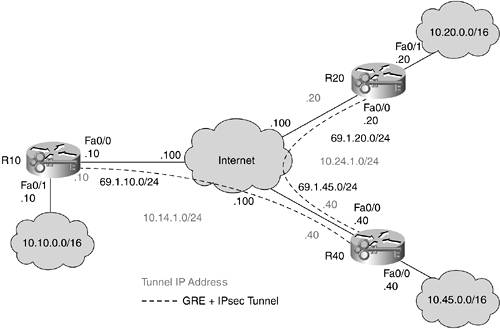
Noteworthy differences in the following configurations as compared to basic IPsec are the addition of a routing protocol and the GRE interfaces. IPsec, in this case, can also run in transport mode instead of tunnel mode to reduce the amount of wasted bytes in the headers. As mentioned earlier, certain hardware acceleration devices for IPsec are optimized for tunnel mode, so check for this on your own gear before making your choice. R40 is acting as the head end. R20 and R10 can no longer communicate directly with one another, so they must first route all traffic through R40.
The IPsec-relevant portions of R40's configuration are as follows:
version 12.2
!
hostname r40
!
! Specify the IKE policy. Notice that this is identical to the IKE policy for
! the basic IPsec configuration.
crypto isakmp policy 1
 encr aes 256
 authentication pre-share
 group 5
crypto isakmp key W"&C66T{MrxSMwhy address 69.1.20.20
crypto isakmp key |n%;(_o(mi,iR`K1 address 69.1.10.10
!
! Specify the IPsec options. This also is identical, with the exception of
! transport mode instead of tunnel mode for the ESP encapsulation.
crypto ipsec transform-set dsen esp-aes 256 esp-sha-hmac
 mode transport
!
! The crypto map configuration is similarly identical with the exception of a new
! command added to the beginning of the configuration. This specifies the source
! identity of the IPsec peer and is helpful to specify with both real and virtual
! interfaces configured on the router.
crypto map vpn local-address FastEthernet0/0
crypto map vpn 10 ipsec-isakmp
 set peer 69.1.10.10
 set transform-set dsen
 set pfs group5
 match address 101
crypto map vpn 20 ipsec-isakmp
 set peer 69.1.20.20
 set transform-set dsen
 set pfs group5
 match address 102
!
! Specify the GRE tunnel to R10. Notice the MTU is set to 1438 to minimize
! fragmentation. Keepalives are also specified, without them the GRE
! interface will always appear to be "UP UP" even if the remote peer
! is not reachable. While this is not strictly necessary for
! connectivity (routing protocols will fail if the link is
! not up) I always prefer to know the real state of each interface.
! This can help in troubleshooting. The GRE tunnel source
! interface is set to the outbound FastEthernet interface and the tunnel
! destination is specified as the remote IPsec peer address.
interface Tunnel0
 ip address 10.14.1.40 255.255.255.0
 ip mtu 1438
 keepalive 10 3
 tunnel source FastEthernet0/0
 tunnel destination 69.1.10.10
!
! GRE configuration for the connection to R20
interface Tunnel1
 ip address 10.24.1.40 255.255.255.0
 ip mtu 1438
 keepalive 10 3
 tunnel source FastEthernet0/0
 tunnel destination 69.1.20.20
!
! The crypto map is still applied to the physical interface just as in the basic
! IPsec example. (older versions of IOS (prior to 12.2(13)T) require it applied
! to the tunnel interface as well).
interface FastEthernet0/0
 ip address 69.1.45.40 255.255.255.0
 crypto map vpn
!
interface FastEthernet0/1
 ip address 10.45.0.40 255.255.0.0
!
! Basic EIGRP routing is configured to allow for dynamic routing. Running a
! routing protocol across your VPN also has the ancillary benefit of
! keeping the IPsec link up at all times.
router eigrp 100
 network 10.0.0.0
 auto-summary
!
ip route 0.0.0.0 0.0.0.0 69.1.45.100
!
! Here you can see the ACLs are modified to only include GRE traffic from the
! local Fa0/0 interface to the remote IPsec peer addresses. Notice that the
! ACLs only need to permit gre traffic since the traffic is already
! encapsulated by the time it reaches the IPsec process
access-list 101 permit gre host 69.1.45.40 host 69.1.10.10
access-list 102 permit gre host 69.1.45.40 host 69.1.20.20
As you can see by the length of this configuration for just two spokes, the configuration effort increases as spokes are added. This is where the dynamic multipoint VPN discussed in the next section can add real value.
The IPsec-relevant portions of R10's configuration are as follows:
version 12.2
!
hostname r10
!
! The IKE policy is identical to the previous configuration
crypto isakmp policy 1
 encr aes 256
 authentication pre-share
 group 5
! Since it is no longer a full mesh network, only one key is specified.
crypto isakmp key |n%;(_o(mi,iR`K1 address 69.1.45.40
!
! Transport mode is specified here
crypto ipsec transform-set dsen esp-aes 256 esp-sha-hmac
 mode transport
!
! The crypto map for R10 is simplified since there is no mapping to R20
crypto map vpn local-address FastEthernet0/0
crypto map vpn 10 ipsec-isakmp
 set peer 69.1.45.40
 set transform-set dsen
 set pfs group5
 match address 101
!
! The GRE tunnel is specified in the same way as R40
interface Tunnel0
 ip address 10.14.1.10 255.255.255.0
 ip mtu 1438
 keepalive 10 3
 tunnel source FastEthernet0/0
 tunnel destination 69.1.45.40
!
interface FastEthernet0/0
 ip address 69.1.10.10 255.255.255.0
 crypto map vpn
!
interface FastEthernet0/1
 ip address 10.10.0.10 255.255.0.0
!
router eigrp 100
 network 10.0.0.0
 auto-summary
!
ip route 0.0.0.0 0.0.0.0 69.1.10.100
!
! Again, the GRE tunnel is the only matching element in the ACL.
access-list 101 permit gre host 69.1.10.10 host 69.1.45.40
The configuration for R20 is identical to that of R10 except for key and IP address differences.
The IPsec-relevant portions of R20's configuration are as follows:
version 12.2
!
hostname r20
!
crypto isakmp policy 1
 encr aes 256
 authentication pre-share
 group 5
crypto isakmp key W"&C66T{MrxSMwhy address 69.1.45.40
!
crypto ipsec transform-set dsen esp-aes 256 esp-sha-hmac
 mode transport
!
crypto map vpn local-address FastEthernet0/0
crypto map vpn 10 ipsec-isakmp
 set peer 69.1.45.40
 set transform-set dsen
 set pfs group5
 match address 101
!
interface Tunnel0
 ip address 10.24.1.20 255.255.255.0
 keepalive 10 3
 tunnel source FastEthernet0/0
 tunnel destination 69.1.45.40
!
interface FastEthernet0/0
 ip address 69.1.20.20 255.255.255.0
 crypto map vpn
!
interface FastEthernet0/1
 ip address 10.20.0.20 255.255.0.0
!
router eigrp 100
 network 10.0.0.0
 auto-summary
!
ip route 0.0.0.0 0.0.0.0 69.1.20.100
!
access-list 101 permit gre host 69.1.20.20 host 69.1.45.40
From a routing perspective, each spoke shows a full complement of routes to each other spoke. When deploying a large number of spokes, summarization at the hub helps keep the route tables small on each spoke. The following shows the output of show ip route on R20:
r20#show ip route
Codes: C - connected, S - static, R - RIP, M - mobile, B - BGP
 D - EIGRP, EX - EIGRP external, O - OSPF, IA - OSPF inter area
 N1 - OSPF NSSA external type 1, N2 - OSPF NSSA external type 2
 E1 - OSPF external type 1, E2 - OSPF external type 2
 i - IS-IS, L1 - IS-IS level-1, L2 - IS-IS level-2, ia - IS-IS inter area
 * - candidate default, U - per-user static route, o - ODR
 P - periodic downloaded static route

Gateway of last resort is 69.1.20.100 to network 0.0.0.0

 69.0.0.0/24 is subnetted, 1 subnets
C 69.1.20.0 is directly connected, FastEthernet0/0
 10.0.0.0/8 is variably subnetted, 5 subnets, 2 masks
D 10.10.0.0/16 [90/310046976] via 10.24.1.40, 00:30:33, Tunnel0
D 10.14.1.0/24 [90/310044416] via 10.24.1.40, 00:30:33, Tunnel0
C 10.24.1.0/24 is directly connected, Tunnel0
C 10.20.0.0/16 is directly connected, FastEthernet0/1
D 10.45.0.0/16 [90/297246976] via 10.24.1.40, 00:30:33, Tunnel0
S* 0.0.0.0/0 [1/0] via 69.1.20.100
HA GRE Hub and Spoke
Figure 10-31 shows the topology for an HA GRE hub-and-spoke design. Note that the GRE tunnel IP addresses are not shown to avoid cluttering the diagram. They are defined in the same manner as the previous design.
Figure 10-31. HA GRE Hub-and-Spoke Design
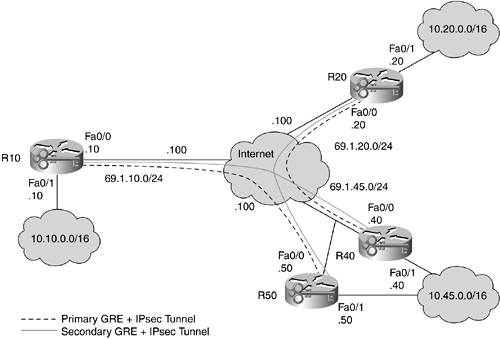
Here you can see that R10 has a primary tunnel to R50 and a secondary tunnel to R40. R20 is configured just the opposite. Bandwidth metrics are placed on the GRE links to specify path preference. Since most of the configuration for these devices is the same, only R50's and R10's configurations are shown.
The IPsec-relevant portions of R50's configuration are as follows:
version 12.2
!
hostname r50
!
crypto isakmp policy 1
 encr aes 256
 authentication pre-share
 group 5
! Here 2 new keys are defined for the connections to R10 and R20
crypto isakmp key 0uHgp;':;RHCSB^ address 69.1.20.20
crypto isakmp key kILNt`iBe8Syoby) address 69.1.10.10
!
crypto ipsec transform-set dsen esp-aes 256 esp-sha-hmac
 mode transport
!
crypto map vpn local-address FastEthernet0/0
crypto map vpn 10 ipsec-isakmp
 set peer 69.1.10.10
 set transform-set dsen
 set pfs group5
 match address 101
crypto map vpn 20 ipsec-isakmp
 set peer 69.1.20.20
 set transform-set dsen
 set pfs group5
 match address 102
!
! GRE interfaces default to 9Kbps in default bandwidth. In order to have a
! particular GRE tunnel be preferred over another, you merely modify
! the bandwidth up or down depending on the desired result. Here,
! since R50 is primary for R10, the GRE tunnel to R10 is given
! a bandwidth statement of 1000Kbps
interface Tunnel0
 bandwidth 1000
 ip address 10.15.1.50 255.255.255.0
 ip mtu 1438
 keepalive 10 3
 tunnel source FastEthernet0/0
 tunnel destination 69.1.10.10
!
interface Tunnel1
 ip address 10.25.1.50 255.255.255.0
 ip mtu 1438
 keepalive 10 3
 tunnel source FastEthernet0/0
 tunnel destination 69.1.20.20
!
interface FastEthernet0/0
 ip address 69.1.45.50 255.255.255.0
 crypto map vpn
!
interface FastEthernet0/1
 ip address 10.45.0.50 255.255.0.0
!
router eigrp 100
 network 10.0.0.0
 auto-summary
!
ip route 0.0.0.0 0.0.0.0 69.1.45.100
!
access-list 101 permit gre host 69.1.45.50 host 69.1.10.10
access-list 102 permit gre host 69.1.45.50 host 69.1.20.20
The IPsec-relevant portions of R10's configuration are as follows:
version 12.2
!
hostname r10
!
crypto isakmp policy 1
 encr aes 256
 authentication pre-share
 group 5
! The key for R50 is added to the configuration
crypto isakmp key |n%;(_o(mi,iR`K1 address 69.1.45.40
crypto isakmp key kILNt`iBe8Syoby) address 69.1.45.50
!
crypto ipsec transform-set dsen esp-aes 256 esp-sha-hmac
 mode transport
!
! A second crypto map instance is added for the connection to R50.
crypto map vpn local-address FastEthernet0/0
crypto map vpn 10 ipsec-isakmp
 set peer 69.1.45.40
 set transform-set dsen
 set pfs group5
 match address 101
crypto map vpn 20 ipsec-isakmp
 set peer 69.1.45.50
 set transform-set dsen
 set pfs group5
 match address 102
!
interface Tunnel0
 ip address 10.14.1.10 255.255.255.0
 ip mtu 1438
 keepalive 10 3
 tunnel source FastEthernet0/0
 tunnel destination 69.1.45.40
!
! Since R50 is the primary head end for R10, bandwidth is set higher to cause
! R10 to prefer the link to R50 over the link to R40
interface Tunnel1
 bandwidth 1000
 ip address 10.15.1.10 255.255.255.0
 ip mtu 1438
 keepalive 10 3
 tunnel source FastEthernet0/0
 tunnel destination 69.1.45.50
!
interface FastEthernet0/0
 ip address 69.1.10.10 255.255.255.0
 crypto map vpn
!
interface FastEthernet0/1
 ip address 10.10.0.10 255.255.0.0
!
router eigrp 100
 network 10.0.0.0
 auto-summary
!
ip route 0.0.0.0 0.0.0.0 69.1.10.100
!
access-list 101 permit gre host 69.1.10.10 host 69.1.45.40
access-list 102 permit gre host 69.1.10.10 host 69.1.45.50
When you look at the routing table for R10, you can see these preferences reflected in the routing:
r10#sho ip route
Codes: C - connected, S - static, R - RIP, M - mobile, B - BGP
 D - EIGRP, EX - EIGRP external, O - OSPF, IA - OSPF inter area
 N1 - OSPF NSSA external type 1, N2 - OSPF NSSA external type 2
 E1 - OSPF external type 1, E2 - OSPF external type 2
 i - IS-IS, L1 - IS-IS level-1, L2 - IS-IS level-2, ia - IS-IS inter area
 * - candidate default, U - per-user static route, o - ODR
 P - periodic downloaded static route

Gateway of last resort is 69.1.10.100 to network 0.0.0.0

 69.0.0.0/24 is subnetted, 1 subnets
C 69.1.10.0 is directly connected, FastEthernet0/0
 10.0.0.0/8 is variably subnetted, 7 subnets, 2 masks
C 10.10.0.0/16 is directly connected, FastEthernet0/1
C 10.15.1.0/24 is directly connected, Tunnel1
C 10.14.1.0/24 is directly connected, Tunnel0
D 10.25.1.0/24 [90/310044416] via 10.15.1.50, 00:22:02, Tunnel1
D 10.24.1.0/24 [90/28162560] via 10.15.1.50, 00:12:07, Tunnel1
D 10.20.0.0/16 [90/28165120] via 10.15.1.50, 00:11:58, Tunnel1
D 10.45.0.0/16 [90/15362560] via 10.15.1.50, 00:12:30, Tunnel1
S* 0.0.0.0/0 [1/0] via 69.1.10.100
If R50 goes down, R40 takes over for R10's traffic as quickly as the routing protocol is configured to converge. Here you can see the console message after the failure and the new routing table:
[View full width]
3d17h: %DUAL-5-NBRCHANGE: IP-EIGRP 100: Neighbor 10.15.1.50 (Tunnel1) is down: holding  time expired r10#sho ip route Codes: C - connected, S - static, R - RIP, M - mobile, B - BGP D - EIGRP, EX - EIGRP external, O - OSPF, IA - OSPF inter area N1 - OSPF NSSA external type 1, N2 - OSPF NSSA external type 2 E1 - OSPF external type 1, E2 - OSPF external type 2 i - IS-IS, L1 - IS-IS level-1, L2 - IS-IS level-2, ia - IS-IS inter area * - candidate default, U - per-user static route, o - ODR P - periodic downloaded static route Gateway of last resort is 69.1.10.100 to network 0.0.0.0 69.0.0.0/24 is subnetted, 1 subnets C 69.1.10.0 is directly connected, FastEthernet0/0 10.0.0.0/8 is variably subnetted, 7 subnets, 2 masks C 10.10.0.0/16 is directly connected, FastEthernet0/1 C 10.15.1.0/24 is directly connected, Tunnel1 C 10.14.1.0/24 is directly connected, Tunnel0 D 10.25.1.0/24 [90/322844416] via 10.14.1.40, 00:00:09, Tunnel0 D 10.24.1.0/24 [90/310044416] via 10.14.1.40, 00:00:10, Tunnel0 D 10.20.0.0/16 [90/310046976] via 10.14.1.40, 00:00:11, Tunnel0 D 10.45.0.0/16 [90/297246976] via 10.14.1.40, 00:00:11, Tunnel0 S* 0.0.0.0/0 [1/0] via 69.1.10.100
Notice that now all routes go through Tunnel0 to R40. When the link comes back up, the routes will switch back.
3d17h: %LINEPROTO-5-UPDOWN: Line protocol on Interface Tunnel1, changed state to up
3d17h: %DUAL-5-NBRCHANGE: IP-EIGRP 100: Neighbor 10.15.1.50 (Tunnel1) is up: new adjacency
GRE Design Conclusion
As you can see, GRE + IPsec does a good job of making your IPsec network appear and behave much like a private WAN. Configuration complexity is a concern, as is the scalability per box for the routing protocol. For a large network, you will likely need several head-end boxes.
Dynamic Multipoint VPN
In Cisco IOS Release 12.2(13)T, Cisco introduced a new mechanism to establish GRE + IPsec tunnels that uses a protocol called Nonbroadcast Multiaccess (NBMA) Next Hop Resolution Protocol (NHRP). NHRP is described in RFC 2332 and defines an ARP-like functionality for NBMA networks. NHRP allows systems on an NBMA network to learn the addresses of other systems on that same network. In this case, the NBMA network is a multipoint GRE (mGRE) tunnel. In our previous examples, GRE was configured in a point-to-point fashion. In dynamic multipoint VPN (DMVPN), GRE tunnels are multipoint and allow all hubs and spokes to share the same subnet and build dynamic tunnels from spoke to spoke as needed. This technology is too new to recommend as a best practice for current IPsec deployments, and as such, it is not detailed here. For comprehensive information on DMVPN, see the following URL: http://www.cisco.com/univercd/cc/td/doc/product/software/ios122/122newft/122t/122t13/ftgreips.htm. The key benefits of this solution over basic GRE + IPsec are as follows:
- Simplified configuration Because an mGRE tunnel is built using the new crypto ipsec profile command and NHRP, the lines of configuration on the hub device are greatly reduced.
- Dynamic spoke addressing Spokes can have their IP address provisioned with DHCP. The identity that is sent to the hub is derived from the tunnel source address for the GRE tunnel (which is updated based on the DHCP address of the interface).
- Spoke-to-spoke communication Spokes are able to dynamically build tunnels to each other based on the NHRP functionality on the mGRE tunnel. This saves load on the hub and prevents spoke-to-spoke traffic from being encrypted and decrypted twice for each packet.
Over time, I expect this technology to mature and be worthy of serious consideration as an alternative to traditional hub-and-spoke GRE + IPsec designs.
Part I. Network Security Foundations
Network Security Axioms
- Network Security Axioms
- Network Security Is a System
- Business Priorities Must Come First
- Network Security Promotes Good Network Design
- Everything Is a Target
- Everything Is a Weapon
- Strive for Operational Simplicity
- Good Network Security Is Predictable
- Avoid Security Through Obscurity
- Confidentiality and Security Are Not the Same
- Applied Knowledge Questions
Security Policy and Operations Life Cycle
- Security Policy and Operations Life Cycle
- You Cant Buy Network Security
- What Is a Security Policy?
- Security System Development and Operations Overview
- References
- Applied Knowledge Questions
Secure Networking Threats
- Secure Networking Threats
- The Attack Process
- Attacker Types
- Vulnerability Types
- Attack Results
- Attack Taxonomy
- References
- Applied Knowledge Questions
Network Security Technologies
- Network Security Technologies
- The Difficulties of Secure Networking
- Security Technologies
- Emerging Security Technologies
- References
- Applied Knowledge Questions
Part II. Designing Secure Networks
Device Hardening
- Device Hardening
- Components of a Hardening Strategy
- Network Devices
- NIDS
- Host Operating Systems
- Applications
- Appliance-Based Network Services
- Rogue Device Detection
- References
- Applied Knowledge Questions
General Design Considerations
- General Design Considerations
- Physical Security Issues
- Layer 2 Security Considerations
- IP Addressing Design Considerations
- ICMP Design Considerations
- Routing Considerations
- Transport Protocol Design Considerations
- DoS Design Considerations
- References
- Applied Knowledge Questions
Network Security Platform Options and Best Deployment Practices
Common Application Design Considerations
- Common Application Design Considerations
- DNS
- HTTP/HTTPS
- FTP
- Instant Messaging
- Application Evaluation
- References
- Applied Knowledge Questions
Identity Design Considerations
- Identity Design Considerations
- Basic Foundation Identity Concepts
- Types of Identity
- Factors in Identity
- Role of Identity in Secure Networking
- Identity Technology Guidelines
- Identity Deployment Recommendations
- References
- Applied Knowledge Questions
IPsec VPN Design Considerations
- IPsec VPN Design Considerations
- VPN Basics
- Types of IPsec VPNs
- IPsec Modes of Operation and Security Options
- Topology Considerations
- Design Considerations
- Site-to-Site Deployment Examples
- IPsec Outsourcing
- References
- Applied Knowledge Questions
Supporting-Technology Design Considerations
- Supporting-Technology Design Considerations
- Content
- Load Balancing
- Wireless LANs
- IP Telephony
- References
- Applied Knowledge Questions
Designing Your Security System
- Designing Your Security System
- Network Design Refresher
- Security System Concepts
- Impact of Network Security on the Entire Design
- Ten Steps to Designing Your Security System
- Applied Knowledge Questions
Part III. Secure Network Designs
Edge Security Design
- Edge Security Design
- What Is the Edge?
- Expected Threats
- Threat Mitigation
- Identity Considerations
- Network Design Considerations
- Small Network Edge Security Design
- Medium Network Edge Security Design
- High-End Resilient Edge Security Design
- Provisions for E-Commerce and Extranet Design
- References
- Applied Knowledge Questions
Campus Security Design
- Campus Security Design
- What Is the Campus?
- Campus Trust Model
- Expected Threats
- Threat Mitigation
- Identity Considerations
- Network Design Considerations
- Small Network Campus Security Design
- Medium Network Campus Security Design
- High-End Resilient Campus Security Design
- References
- Applied Knowledge Questions
Teleworker Security Design
- Teleworker Security Design
- Defining the Teleworker Environment
- Expected Threats
- Threat Mitigation
- Identity Considerations
- Network Design Considerations
- Software-Based Teleworker Design
- Hardware-Based Teleworker Design
- Design Evaluations
- Applied Knowledge Questions
Part IV. Network Management, Case Studies, and Conclusions
Secure Network Management and Network Security Management
- Secure Network Management and Network Security Management
- Utopian Management Goals
- Organizational Realities
- Protocol Capabilities
- Tool Capabilities
- Secure Management Design Options
- Network Security Management Best Practices
- References
- Applied Knowledge Questions
Case Studies
- Case Studies
- Introduction
- Real-World Applicability
- Organization
- NetGamesRUs.com
- University of Insecurity
- Black Helicopter Research Limited
- Applied Knowledge Questions
Conclusions
- Conclusions
- Introduction
- Management Problems Will Continue
- Security Will Become Computationally Less Expensive
- Homogeneous and Heterogeneous Networks
- Legislation Should Garner Serious Consideration
- IP Version 6 Changes Things
- Network Security Is a System
References
Appendix A. Glossary of Terms
Appendix B. Answers to Applied Knowledge Questions
Appendix C. Sample Security Policies
INFOSEC Acceptable Use Policy
Password Policy
Guidelines on Antivirus Process
Index
EAN: 2147483647
Pages: 249
- Enterprise Application Integration: New Solutions for a Solved Problem or a Challenging Research Field?
- Context Management of ERP Processes in Virtual Communities
- Intrinsic and Contextual Data Quality: The Effect of Media and Personal Involvement
- Healthcare Information: From Administrative to Practice Databases
- Relevance and Micro-Relevance for the Professional as Determinants of IT-Diffusion and IT-Use in Healthcare
